My room is about the same size though I use rather powerfull self designed speakers. My concern isn't so much rumble as I don't play back using a turn table, besides, most audio sources don't go that low and are already limited / filtered off in the very lows. What it achieves is flatness and zero phase from the amp all the way down to 20Hz, while still providing the main function of the input capacitor: DC decoupling. In my way of thinking this would allow the original signal to be exposed fully as intended on speakers that can reproduce it. They're 600W/4Ohms nominal, for use with a finished MF500 and consist of Visaton speakers. I don't really want to toot my own horn, but I'm just so proud of them. A tower consists of 2x TIW360 8Ohm, 2x DSM 50 FFL 8OHm and a DSM 25 FFL 4Ohm configured as a 3-way 4Ohm total impedance speaker. It sounds great and they make my MF80 project soar unrestricted ")
As this thread is closely related to layout and decoupling caps. PCB experts are always welcome to vent their views here http://www.diyaudio.com/forums/soli...ly-best-amplifier-galaxy-pcb-phase-2-a-2.html
I hope some of you have tried out this power supply
And a recap
http://www.diyaudio.com/forums/solid-state/216409-power-supply-resevoir-size-6.html#post3098034
http://www.diyaudio.com/forums/solid-state/216409-power-supply-resevoir-size-6.html#post3098067
http://www.diyaudio.com/forums/solid-state/216409-power-supply-resevoir-size-10.html#post3099166
I hope some of you have tried out this power supply
An externally hosted image should be here but it was not working when we last tested it.
And a recap
http://www.diyaudio.com/forums/solid-state/216409-power-supply-resevoir-size-6.html#post3098034
http://www.diyaudio.com/forums/solid-state/216409-power-supply-resevoir-size-6.html#post3098067
http://www.diyaudio.com/forums/solid-state/216409-power-supply-resevoir-size-10.html#post3099166
Last edited:
Yes, in these terms, minimum size power supply for 8 ohm Speaker Support would be the value you'd have to use to be absolutely sure there is not a resistive effect. I do not know. I guess output cap for 8 ohm speaker 3hz, with the value doubled for split rail. There were some assumptions, but you'll get the idea--we're Certain to have the speaker bandwidth intact and that portion of the job done regardless of amplifier power ratings.I don't know what you mean by 'speaker support'. Perhaps LF rolloff at the output? The PSU caps don't behave like an output cap, because the PSU caps get (approximately) clamped to a fixed voltage 100/120 times a second - this makes them behave like a low value resistor rather than a cap, for LF signal voltages.
The new question is how much more than 13,300uF do we need for a Split rail amplifier, And how powerful must the amplifier be prior to incurring the need to increase capacitance further?
Demo: Estimated 3,300uF per ampere figure doesn't work with a miniature single amplifier attached to a very large speaker. Estimation fails if it doesn't output 2 amperes. And it doesn't--in that case the 3,300uF per ampere causes the error of insufficient speaker support. OR, with a very large amplifier the capacitance could be overlarge. The currently state of the art estimations do not work because there are several questions, not just one.
Ah, finally, the point:
Therefore I propose that we set a power supply figure that's big enough for a speaker before worrying about what's big enough for an amplifier. Right?
P.S.
The question of capacitance per ampere already came with one monkey wrench thrown in because there's a speaker attached, but we could throw in an additional monkey wrench by considering decreasing the input cap size of the amplifier (set -0db 44hz or -6db 22hz) whatever would raise the 3hz speaker support figure up to 6hz. Well my maths failed on that one, but you get the point--a tiny bit of efficiency tuning would cut the power supply costs in half.
A little single rail amp tuned so would decrease the power supply from 6600uF to 3,300uF. Now if we suddenly made it a LOT more powerful, how much more capacitance do we need?
That efficiency tuning question is a separate question from speaker support, which is a separate question from capacitance per ampere. There are 3 different questions. Divide and conquer?
Attachments
Last edited:
Here is a small article on understanding RF. This article requires improvement. Looking at this article you are likely to be better off with one large reservoir cap (unless you are using CRC) than several caps without CRC due to the likely hood of the formation of high Q resonant circuits between the capacitors
Attachments
Last edited:
Daniel,
It's late so maybe my brain isn't working well any more but I am not following you at all.
The speaker is already modeled as the load resistance, throughout this entire thread. So the speaker is already included.
And what the heck is "speaker support"?! Please, restate using accepted terminology, so people can more-easily attempt to understand.
Tom
Here is a small article on understanding RF. This article requires improvement. Looking at this article you are likely to be better off with one large reservoir cap (unless you are using CRC) than several caps without CRC due to the likely hood of the formation of high Q resonant circuits between the capacitors
Is there a link to where you found this article?
Speaker (frequency response) support: AndrewT's post at #759 "amplifier must be able to perform well down to ~ 2Hz to 3Hz"The speaker is already modeled as the load resistance, throughout this entire thread. So the speaker is already included.
Conflicts with: 8 ohm speaker, 50 watts, 240 va, Cmin Actual of 3600uF.
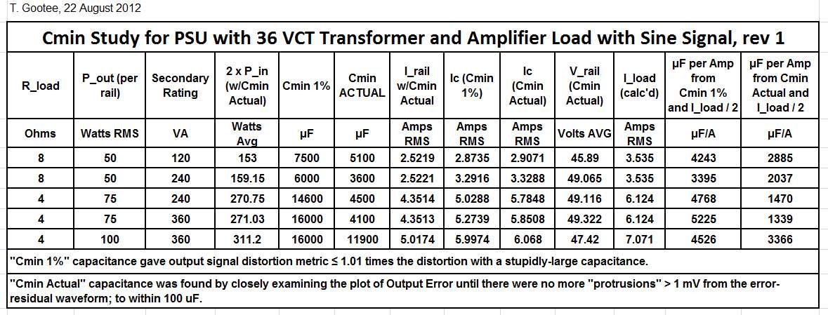
That chart has a narrow sample range.
But, a wide sample range could be so much more informative:
1w amplifier supporting 8 ohm speaker to 3hz
2w amplifier supporting 8 ohm speaker to 3hz
4w amplifier supporting 8 ohm speaker to 3hz
8w amplifier supporting 8 ohm speaker to 3hz
16w amplifier supporting 8 ohm speaker to 3hz
32w amplifier supporting 8 ohm speaker to 3hz
64w amplifier supporting 8 ohm speaker to 3hz
128w amplifier supporting 8 ohm speaker to 3hz
256w amplifier supporting 8 ohm speaker to 3hz
512w amplifier supporting 8 ohm speaker to 3hz
1024w amplifier supporting 8 ohm speaker to 3hz
The amplifier power is changed. The frequency response requirement is fixed.
With such a broad range, a minimum required capacitance line graph will be fascinating (and an easy read if capacitance per watt). I'm sure that yours will be much more accurate than mine.
No, I don't get "the idea". As gootee says, we don't know what you are talking about. 'Speaker support' is not a recognised term in audio engineering.danielwritesbac said:There were some assumptions, but you'll get the idea
Let's be clear: PSU caps are doing a different job from the output cap used by a single-rail amplifier. You can't compare their values as though they are doing the same job. PSU caps only start doing the same job when the power is switched off! Not many people listen to music with the power switched off.
No, I don't get "the idea". As gootee says, we don't know what you are talking about. 'Speaker support' is not a recognised term in audio engineering.
Let's be clear: PSU caps are doing a different job from the output cap used by a single-rail amplifier. You can't compare their values as though they are doing the same job. PSU caps only start doing the same job when the power is switched off! Not many people listen to music with the power switched off.
In that respect, power is switched off every time the rectifying diodes stop conducting and this happens at least 50 times in a second.
Correct?
I meant switched off so the 100/120Hz clamping action no longer happens; I think that should be obvious. At high frequencies (not what we are talking about here) the PSU caps act like an output cap. At low frequencies (what we are talking about here) the clamping changes the behaviour - in effect the PSU caps act like a cap in parallel with a low value resistor, and the resistor can dominate the LF behaviour.
Remember, at DC the cap has infinite impedance yet the supply still has a finite and low impedance due to the clamping action. Similarly true for LF.
Remember, at DC the cap has infinite impedance yet the supply still has a finite and low impedance due to the clamping action. Similarly true for LF.
I totally support the idea of the lowfrequency speaker current driving cap...This is the last cap before/in the output sectoion.. before that and R separated is the other side of the PSU. the DC smoothing and charging section, this section should reduce ripple to a minimum.
funny thing.. i have made some phono-stages and for this made different types of supplies.. from cap multiplier over led set shunts, to be honest the best sounding are the CRCRCR types, for some reason they present music on a darker background and presents it in a way that makes more sense....!!!
Here this approach with a type of split supply I'm dead sure will do the same for Power-amps... I'm confident that the low cut off frequency approach for the speaker impedance is a feasible path for setting a value on the second bank...hence the DC-bank for the charging needs more attention...
Just to clarify: I am assuming that there is a negligibly low impedance at LF between the reservoir caps and any separate smoothing caps. This will normally be the case for a power amp, otherwise the supply is likely to be very inefficient. In many cases there are no separate smoothing caps, just a local decoupler on the amp. Chokes are rare in this application. A regulated supply places a low LF impedance across the final caps too.
Well that might be a bit tardy. Anyway, thank you for explaining the problem.'Speaker support' is not a recognised term in audio engineering.
Last edited:
What he means by that is the required design specs and component values to drive a given speaker impedance treshold. "Speaker support of 8Ohm" would probably mean an amp designed to drive an 8 ohm speaker at a minimum.
There's not really a term for that, other than the encompassing "minimum design specifications".
There's not really a term for that, other than the encompassing "minimum design specifications".
I still don't know what he means. He obviously feels it has something to do with PSU caps, yet separately from their role as temporary charge stores.
To me 'speaker support' is the stand on which a loudspeaker sits, so that it no longer interacts directly with the ground/carpet in front of it. Nothing to do with reservoir caps.
To me 'speaker support' is the stand on which a loudspeaker sits, so that it no longer interacts directly with the ground/carpet in front of it. Nothing to do with reservoir caps.
"With such a broad range, a minimum required capacitance line graph will be fascinating (and an easy read if capacitance per watt). I'm sure that yours will be much more accurate than mine".
If the case for this argument could be taken to be realistic could not there be a chart showing two lines. One line showing the minimum transformer size and matching large capacitor requirement and a second line with maximized transformer size and the minimum capacitor values given a stated load impedance at the loudspeaker and power output maximum with 0.1% distortion requirement? This would seem to give a min/max SOA area of choice for the two components.
If the case for this argument could be taken to be realistic could not there be a chart showing two lines. One line showing the minimum transformer size and matching large capacitor requirement and a second line with maximized transformer size and the minimum capacitor values given a stated load impedance at the loudspeaker and power output maximum with 0.1% distortion requirement? This would seem to give a min/max SOA area of choice for the two components.
Is there a link to where you found this article?
Its the original. Drafted it before I nodded off last night. Heres a question for everyone to contribute
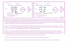
. Should unused windings in a transformer be properly terminated ? Just like we terminate unused opamps ?
Last edited:
I will look into expanding the table I made, Daniel.
And AP2, I have not forgotten about the transient burst response.
I finally figured out how to automate the measurement of pulse/square distortion! All I had to do was create two parameterized "marker" voltage sources, to use to define the TRIG and TARG points for the LT-Spice .meas commands, in order to be able to accurately define the intervals over which the measurements are made. Now I can repeatably accurately measure the RMS, P-P, MAX, and/or MIN, over only the time intervals when the pulse tops should be flat (or only during rise and fall times, if I wanted).
So now I can create plots of relative distortion versus reservoir capacitance when using square wave signals, by measuring, for example, the RMS value of the calculated output error, during the time-intervals corresponding to the pulse tops and bottoms, probably summed over the same fixed number of cycles starting at the same particular time for each scenario, in this case.
I will post the LT-Spice files and some results over the weekend.
This type of setup should also be a very good starting point for getting some kind of comparable measurements of transient responses, that could be used when investigating and characterizing the effects of varying decoupling capacitance.
Cheers,
Tom
Last edited:
- Status
- This old topic is closed. If you want to reopen this topic, contact a moderator using the "Report Post" button.
- Home
- Amplifiers
- Power Supplies
- Power Supply Resevoir Size