Guys. Rather than hypothesizing, I suggest that you pick up a text on medical electronics. The safety aspects are usually covered in the first chapter or two. I can dig out a reference if there's sufficient interest.
The model above is not too far off if intended to model a hand-to-hand shock. However, note that the resistances are non-linear and dependent on a whole slew of variables (including voltage). The resistances are much lower if you sweat or have a high stress level. Stress alone can change the resistance arm-to-arm by an order of magnitude(!)
The current tends to follow the bones. This is what makes it possible to survive a large shock without cardiac arrest. The heart is relatively far away from the bones in the chest, hence, little current flows through the heart whereas the majority of the current flows along the rib cage.
The magnitude of the current through the heart plays a role as well. At very low currents, nothing happens. At medium currents there is a high probability of heart fibrillation. At higher currents, there's actually less chance of fibrillation and cardiac arrest. And at even higher currents, tissue burns, your organs get cooked, and you really have bigger things to worry about than the cardiac arrest you just had.
I seem to recall "low" to be <500 uA; "medium" 0.5~5 mA; and "higher" upwards of 1 A. That's free from memory and I don't recall if that's arm-to-arm or through the heart itself. I can look it up tonight.
~Tom

Simple question :
Why defibrillators indicates Joules instead of mA ?
Maybe because of the time variable?
Maybe because of the time variable?
Exactly. The defib probably works by discharging a capacitor through the body, but since the body's resistance varies a lot, the current could be anything, so there's no point in trying to specify a current. The energy delivered from the defib's capacitors, however, is known.
Last edited:
To make it simple,
Voltage is pressure across the resistance and current is the amount of flow..
High current / low voltage can give high energy
low current / high voltage can give the same energy
V * A = Watts ....so 1V*2A= 2W 2V*1A=2W
So whats it all about...everything will conduct...
If you put enough pressure (Volts) across it think lightning the air conducts..
The damage is how much flow after the pressure brakes down the resistance to flow...
Once this happens the resistance reduces due to the burning effect of the current...
Then it takes less voltage to maintain the same or more current..the burning then allows more current and more burning..the longer the contact the worse it gets...
So inside your body is water and salt..the skin if dry or wet and the amount of current that will flow after the voltage overcomes the initial resistance of the skin..
The contact area has an effect on the heating or burning..think small contact point more burning large contact point less burning..
Thats why a diathermy unit has a large pad on the back of the patient..if contact is reduced (the pad loses connection) the pad will burn the patient..
Surgical-tutor.org.uk - a free online surgical resource
The voltage like any resistor is dropped across the body...ie if 100V is across the body you would expect something like 50V in the middle..if the voltage dropped across the heart is enough for current to interrupt the operation you will go into cardiac arrest..if the current stops because you let go you may recover..if you can't let go with some DC systems then you will have a problem..

Don't assume AC will allow you to let go it depends on how bad the shock is and what effect its having on the muscles...
EG in very high power industry the muscles can contract so violently that the bones in the body break and can be ejected out of the foot or elbow..
This is very high current and not normally DIY level..
A shock across the body is worse than down the body..why well whats on your feet...is it skin to metal contact whats the resistance etc
Regards
M. Gregg
Voltage is pressure across the resistance and current is the amount of flow..
High current / low voltage can give high energy
low current / high voltage can give the same energy
V * A = Watts ....so 1V*2A= 2W 2V*1A=2W
So whats it all about...everything will conduct...
If you put enough pressure (Volts) across it think lightning the air conducts..
The damage is how much flow after the pressure brakes down the resistance to flow...
Once this happens the resistance reduces due to the burning effect of the current...
Then it takes less voltage to maintain the same or more current..the burning then allows more current and more burning..the longer the contact the worse it gets...
So inside your body is water and salt..the skin if dry or wet and the amount of current that will flow after the voltage overcomes the initial resistance of the skin..
The contact area has an effect on the heating or burning..think small contact point more burning large contact point less burning..
Thats why a diathermy unit has a large pad on the back of the patient..if contact is reduced (the pad loses connection) the pad will burn the patient..
Surgical-tutor.org.uk - a free online surgical resource
The voltage like any resistor is dropped across the body...ie if 100V is across the body you would expect something like 50V in the middle..if the voltage dropped across the heart is enough for current to interrupt the operation you will go into cardiac arrest..if the current stops because you let go you may recover..if you can't let go with some DC systems then you will have a problem..
Don't assume AC will allow you to let go it depends on how bad the shock is and what effect its having on the muscles...
EG in very high power industry the muscles can contract so violently that the bones in the body break and can be ejected out of the foot or elbow..
This is very high current and not normally DIY level..
A shock across the body is worse than down the body..why well whats on your feet...is it skin to metal contact whats the resistance etc
Regards
M. Gregg
Last edited:
Fast high current,
Is worse it has an explosive effect..blows holes in skin and bone..Thats why large capacitor banks need to be carefully discharged..High voltage high capacitance is worse than low cap values with the same voltage..energy release and speed of release..
Long low current heating is slower in a given area..so if you can't let go you get a slow cook effect...the blood boils and the body goes like stone..
The high current high voltage can do the same thing in short time..
The medusa effect...people locked in position, muscles burnt, blood solid in the limbs (like black pudding)..not always dead..at the accident but die later in hospital..dehydration..This tends to be industrial level currents..
You also get things like the tongue bitten off involuntary muscle reaction and people thown across areas and impact injury..like the guy behind the person getting the shock gets an elbow in the face...
Regards
M. Gregg
Last edited:
Think microwave,
Long low current bacon dried out and stiff...high energy, BANG bits of skin and holes in the contact and depart areas of the current..a bit like a bullet the contact areas on current in and current out get heated instantly and the body heats up over a longer period.. Once carbon build up happens current flow increases..temp goes up and cooks..
I remember doing some work with guys in a hospital theater when I walked in they breathed in deep and said oh smell the diathermy..dosen't it make you feel hungry.....I didn't know what to say...
I couldn't eat my breakfast after I kept remembering the smell..
Regards
M. Gregg
Long low current bacon dried out and stiff...high energy, BANG bits of skin and holes in the contact and depart areas of the current..a bit like a bullet the contact areas on current in and current out get heated instantly and the body heats up over a longer period.. Once carbon build up happens current flow increases..temp goes up and cooks..
I remember doing some work with guys in a hospital theater when I walked in they breathed in deep and said oh smell the diathermy..dosen't it make you feel hungry...
..I didn't know what to say...I couldn't eat my breakfast after I kept remembering the smell..
Regards
M. Gregg
Last edited:
The main thing is,
You have to build the circuit as required, then remember at the end of the day if its dead before you work on it, it should be OK. If your testing then your NOT WORKING on it. You shouldn't be removing covers to test with it switched on.
Assuming that all the discharge is in place..safety fuses, transient suppression, ripple filtering, RFI filtering, soft starts, heater suppression, correct ratings for the power TX, Type of Tx, earthing and any Ground suppression, lifting or star/ground plane, types of diodes, or tube rectifiers, types of wire and capacitor, transformer mounting, split supplies, dual supplies are in place.
So power supplies...your building for fast release of energy for transient..the faster the better..fast recharge (Recovery time) ready for the next transient.
You need to be able to supply the current demand so you don't get sag (voltage drop on the supply rail during transient). Minimum ripple, low RFI, etc.
Back to topic "the best way to achieve this".
Regards
M. Gregg
Why aren't switched mode power supplies common in tube amplifiers?
Maybe it could be used for bias. The 400v DC source inside the supply would seem ideal for the output stage of a tube amp. The 12v may be ok for some preamp tubes. Would the 5v be enough for lighting 6v heaters?
Heaters should be run at 6.3V if you put 2 in series then thats 12.6 not 12V.
The B+ can create some strange sounding music from the amp but it can be done.
From the point of view of bias..remember the bias is connected to the tube grid in some situations and so any ripple is a direct input..
I'm not sure how isolated a tube's filament is from the rest of the tube. Could a pair of PP output filaments be wired in series for 12v without effecting the function of the tube?
Remember some tube filaments need lifting so how are you going to lift a tube heater that is common to the DC HT rail? Yes you can run heaters in series it was done in old TVs the main thing is to isolate the mains from the circuit for both heaters and B+<<its a must do!
Another cheap switched mode supply is electronic ballasts used in fluorescent lighting. Maybe it could be used as is or modified for tube use. My concern with it is that some may not be 100% isolated from the ac line.
The biggest problem is ripple and RFI you can use inverters I have done it for fun with an SRPP stage aikido line amp..the big problem was isolating the heaters..also the current needed for the HT B+.
Thoughts?
Simple question :
Why defibrillators indicates Joules instead of mA ?
Maybe because of the time variable?
Without being a doctor, I would say that what kills is the energy absorbed in a certain time interval.
Since the human body in general obeys Ohm's law, that energy, can be expressed in terms of the current and/or voltage.
W = i^2 R = i V = V^2/R [W] = J/s
By analogy, which burns, is the heat absorbed in a certain time interval, not temperature.
When you drink a cup of hot coffee, if you take it in a very short time, you get burned.
Doing it in small sips, as you do every morning, you do not burn.
The absorbed energy is the same, the temperature is the same...
Do you hear me now ?
I hope that we can now speak about PSUs.
OK, as they ask me so insistently, here are some of my own Rules of Dumb.
1) Use valve rectification for +B
I myself thought it was an audio myth, until I experienced it.
The advantage over the SS are not sufficiently clear from the standpoint of theoretical/scientific, but it works and it's wonderful.
As experimental verification, I know of people who, with eyes closed, recognizes the difference in sound.
2) Make regulated PSUs, even for heaters !
With MOSFETs, low noise opamps and precision voltage references.
Series regulation for power amps and shunt regulation for high gain preamps.
Use generous volage drop and capacitances.
3) Elevate heaters
At least 30 V instead of grounding, and at an adequate voltage for each topology.
AC heater power to listen your amplifier, "tube sound"
DC heater power to listen the music.
4) Make soft start for all PSUs, adding a time delay for +B
Valves suffer thermal stress when heating, and ion bombardment starts at about 100 eV, I myself have verified it experimentally !
Here you can see some interesting regulators
Services
1-i like rock hard psuOK, as they ask me so insistently, here are some of my own Rules of Dumb.
1) Use valve rectification for +B
I myself thought it was an audio myth, until I experienced it.
The advantage over the SS are not sufficiently clear from the standpoint of theoretical/scientific, but it works and it's wonderful.
As experimental verification, I know of people who, with eyes closed, recognizes the difference in sound.
2) Make regulated PSUs, even for heaters !
With MOSFETs, low noise opamps and precision voltage references.
Series regulation for power amps and shunt regulation for high gain preamps.
Use generous volage drop and capacitances.
3) Elevate heaters
At least 30 V instead of grounding, and at an adequate voltage for each topology.
AC heater power to listen your amplifier, "tube sound"
DC heater power to listen the music.
4) Make soft start for all PSUs, adding a time delay for +B
Valves suffer thermal stress when heating, and ion bombardment starts at about 100 eV, I myself have verified it experimentally !
Here you can see some interesting regulators
Services
2-understand for direct heaters, but otherwise not
3
4-it makes sense, at least for elyt caps
ion bombardment? if it´s gassy tube, then..

1-i like rock hard psu
Good for you !
2-understand for direct heaters, but otherwise not
AC hum in indirect heating valves, can be introduced into the audio signal through different routes
i) AC heater magnetic field can be induced over the grid and/or cathode.
ii) AC voltage can pass to cathode trough Ckf, Rkf, or via the juction diode formed between heater and cathode .
4-it makes sense, at least for elyt caps
ion bombardment? if it´s gassy tube, then..
No need a gassy tube to observe ion bombardment.
CRTs has the same type cathode as common valves.
http://144.206.159.178/FT/68/73201/1254249.pdf
Ever more, I myself have observed ion bombardment at about 100 eV, without HV anode voltage !
Edit: The link was removed, sorry.
Last edited:
Ion Bombardment
The vacuum in a valve is not perfect, so there are gas molecules randomly floating between the anode and cathode.
If an electron should be accelerated towards the anode from the cathode, there is always a chance that it will collide with a gas molecule and have sufficient energy to remove an electron from that molecule, rendering it positively charged and attracted to a lower potential such as the cathode.
These ions can have a significant momentum when it strikes the cathode.
Case 1: Vak = 0, Hot Cathode
In metals, at normal temperature, the conduction band is essentially filled of electrons only up to the Fermi energy EF, to extract an electron from the metal is therefore necessary to give a starting energy ei, but at high temperatures the occupation of electronic states extends above EF.
If the temperature is high enough, some electrons reach energies greater than EF + ei, and escape from the metal.
If the temperature increases further, the Fermi energy level is widely exceeded and electrons have enough energy to collide with a gas molecule, and have enough energy to remove an electron from that molecule, rendering it positively charged and attracted to a lower potential such as the cathode.
The force acting on the ions, is due to the electric field created by the charge distribution between the cathode and anode, ie. the electron cloud.
F = e E
For simplicity we assume that ions are fermions, then from the Fermi-Dirac distribution, some ions after interacting with the electron cloud, hit the cathode with enough momentum to be absorbed into its surface.
This phenomenon is called "Cathode Poisoning"
Case 2: Vak = B+, Cathode warms from cold
The cathode starts to warm up.
For simplicity we assume that only one electron is emitted, eg. infrared photoelectric effect.
This electron is accelerated toward the anode and assuming that collides with at least one gas molecule, and has enough energy to produce an ion.
Now there is no electron cloud, then the force exerted on the ion, is due to the electric field created by the potential difference between cathode and anode.
F = e E = - e grad (φ)
The ion hit the cathode with enough momentum to produce sputtering in the cathode.
This phenomenon is called "Cathode Stripping"
In a "Gassy Tube" the number of gas molecules is so high, then it produce ionization, but this is another thing...
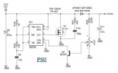
There is a power supply for nixie tubes based on NE555 (there are others, but the idea is the same), that works from dc (less than 18 volts)
and it bumps the voltage up to ~300vdc with a very small current (less than 25mA). So it's possible to power 2 regular 12ax7's from 12v and less than 2A. The problem is that the whole thing can't work with "High" DC voltage because of NE555 will burn out.
So my question is this: if the NE555 was made from a discrete transistor (like 2sc2240/2sa970) that can take up to 120v, does it mean the the efficiency of this circuit will be much higher? It will be much easier to boost 100v to 400v, than 12v to 400v so that it will be capable to deliver enough current to supply power and preamp tubes.
Attachments
- Status
- This old topic is closed. If you want to reopen this topic, contact a moderator using the "Report Post" button.
- Home
- Amplifiers
- Tubes / Valves
- Power supply options for tube amplifiers.