Hi,
irfp240 is a good Nchannel power FET that gives good results in an audio amplifier designed to suit it. It's Pchannel partner is not a good complement.
Please go and read a lot about SOA and how to apply it to output stages.
Pay attention to how the SOA is derated for device temperature and what transient values it can tolerate when operating faster than DC.
Then research how reactive loads become the dominant stress that causes output failure.
Most FET and BJT output stages will fail due to transgressing the SOA curve applicable to the operating and temperature conditions.
Short circuits cause failure due to stupidity not usually due to bad design. Over voltage failure can only happen due to bad design.
Research hint:- find Bensen's spreadsheet and look up the reference in there. Read how to design a driver and output stage to survive reactive loads.
hi
quasi ,
I am planning to build an AV 5 channel amp . I would want to build an amp with 5 channels and a subwoofer channel . It would basically be a 5.1 amp .
For the subwoofer I would like to use the 10 fet board and for the 5 channels ,i would like to use a pair of outputs for each channel .
Do you have any layout for using a pair of fets for each board ,so that I would be having a smaller footprint board and subsequently save on the costs as well .
Many thanks
Re: hi
You might be better off building chip-amps for the 5 channels. These will take up much less room for the same power as a 2 FET quasi board.
Cheers
Q
yugaaa said:quasi ,
I am planning to build an AV 5 channel amp . I would want to build an amp with 5 channels and a subwoofer channel . It would basically be a 5.1 amp .
For the subwoofer I would like to use the 10 fet board and for the 5 channels ,i would like to use a pair of outputs for each channel .
Do you have any layout for using a pair of fets for each board ,so that I would be having a smaller footprint board and subsequently save on the costs as well .
Many thanks
You might be better off building chip-amps for the 5 channels. These will take up much less room for the same power as a 2 FET quasi board.
Cheers
Q
Re: Re: hi
but 200W per "chanal" no chip can make: usualy chips has less aond qualitiy ?
quasi said:
You might be better off building chip-amps for the 5 channels. These will take up much less room for the same power as a 2 FET quasi board.
Cheers
Q
but 200W per "chanal" no chip can make: usualy chips has less aond qualitiy ?
Re: Re: hi
Well ,I do have a 5 channel tda7393 amplifier . I am planning on an upgrade and I should say ,I want something discrete these days . After building the amplifier I know chip amps are not to my taste .
Well, I think I will go ahead and try redoing the layout ,but ,I did like to know if irfp240 would work fine as a single pair and considering the fact i might be using a minimum 4R load ,what voltage would you recommend ,so that the amplifier might operate without smoke
many thanks
quasi said:
You might be better off building chip-amps for the 5 channels. These will take up much less room for the same power as a 2 FET quasi board.
Cheers
Q
Well ,I do have a 5 channel tda7393 amplifier . I am planning on an upgrade and I should say ,I want something discrete these days . After building the amplifier I know chip amps are not to my taste .
Well, I think I will go ahead and try redoing the layout ,but ,I did like to know if irfp240 would work fine as a single pair and considering the fact i might be using a minimum 4R load ,what voltage would you recommend ,so that the amplifier might operate without smoke
many thanks
Hi Yug,
For a 5.1 system this is best met by using either stereo amplifiers or monoblocks, NOT by running speaker cables around the room.
+-50Vdc will give upto 200W into 4r and +-60Vdc upto 300W into 4r.
If you want extreme SPLs with low sensitivty speakers then +-70Vdc could go upto 400W into 4r.
With 6channel that's 2.4kW and an expensive set of transformers and smoothing caps.
yes, keep the amplifiers next to the speakers or at a very maximum no more than 2m from the speakers.Do you have any layout
For a 5.1 system this is best met by using either stereo amplifiers or monoblocks, NOT by running speaker cables around the room.
+-50Vdc will give upto 200W into 4r and +-60Vdc upto 300W into 4r.
If you want extreme SPLs with low sensitivty speakers then +-70Vdc could go upto 400W into 4r.
With 6channel that's 2.4kW
and an expensive set of transformers and smoothing caps.Re[02]: hi
yugaaa,
I created 1, 2 and 4 pair boards about year ago with careful editing using GIMP. Since that time a flaw was discovered by Shawn on the PCB that explained many of the VBE adjustment problems many had. I have had a plan to redo the boards since they were updated for both versions (with and without DC protection circuit on same board) as well as make the DC protection seperate. the edits are time consuing, generally about 45 minutes a image, so a days work if all goes well without my human errors to make up the images.
I had also started a super guide that would reduce the common repeated questions asked of quasi. I started the document, but have not had the time in last 9+ months to work on in further. I hope to be able to, but it will take at least 2 months of solid work to compile and organize the information. Qausi's guide will be excellent for many. I do suggest you take the time to read the complete thread before asking any questions. I do not think there is a question, or very few, that have not already been asked or information provided before the question is asked on this thread.
Please read the discussions on SOAR in different places on the thread as many builders wanted to use alternate output MOSFET devices for many different reasons. You may find you wish to build the 2 pair verison outright or build with a pair first and then decide later if need to add a pair for better headroom and not pushing the SOAR rating of the IRFP240. There are losts of postings on SOAR specific calculations and simple calculations to allow you to determine how many output devices you will want to ensure the output devices are not blown.
I have have kept an eye on this thread and now the BiPolar version quasi recently opened. I have not been able to spend time on my interests since the summer due to personal matters and then overloaded with being a daddy to 6 kittens that were 3.5 weeks old found not far from where I live the first weekend of September. This is ontop of my 4 adult cats, who are walk on leashes. You can imagine how this approach filters down to the kittens getting time outside as well as their other normal demands as kittens.
Here are the links to get you started based on above as it will be a few months yet before I hope to be out of the current personal matter concerns:
Link to where I announced the site I have the noted different board versions with DC protection 11 Dec 2005, Post #253:
http://www.diyaudio.com/forums/showthread.php?postid=787264#post787264
Error 200 ohm Pot (hard to set BIAS), Post #1017:
http://www.diyaudio.com/forums/showthread.php?postid=996473#post996473
Re: Error 200 ohm Pot (hard to set BIAS), Post #1024:
http://www.diyaudio.com/forums/showthread.php?postid=996553#post996553
Quasi, please correct me if I am wrong, but this Vbe PCB error was the only error on the PCB aside from a couple of parts on the PCB that were on the PCB, but not marked with part or value of part. The 0.01uf cap near T8 seems to come to memory as pads and outline, but no part number nor value on PCB layout image.
Sorry all, I do not have all time in world to find all of these finer points. I can just recall all this off top of my head for now, let alone find links about them that takes lots of time. The Super Guide I started covers all of this and I have many notes to continue its work as many seem impatient to read this thread. I have a hot link table of contents and structure to make all of these common questions, formulas, and design flexibility titbits sprinkled in the thread to make it easy for almost all of those new to thread and unwilling to read the thread.
yugaaa, again I cannot too strongly suggest you read the entire thread to find these subtle things or compare to the board I made of pair, two and four almost year ago. Again quasi's guide will cover all the updates, but I have not had time to edit the boards for the Vbe trace problem Shawn found. It should be easy for you to take one of my .PNG imahes of quasi's board and with editing program "rub" out the extra PCB trace Shawn found.
Post #1123 Latest Schematic:
http://www.diyaudio.com/forums/showthread.php?postid=1008216#post1008216
When life here is more settled then I will catch up on this thread and make related postings. I am not sure when that will be, but not likely until the new year at earliest I suspect. The 6 kittens are more a bit more work, but the first 5 weeks they were a constant effort 24/7 over and above the major personal matters ongoing since start of summer.
yugaaa, this is one very very excellent amp. I have not had time to build, byt many have and are very happy with it. It's design is excellent, has great flexibility with alternate parts with little impact generally speaking on amp sound quality as long as you use good alternate parts. I have not seen a amp so well designed, flexible (i.e. not tied to a unique part quality that changing will make major different, or inability to have a stable amp), very stable if you follow good PSU/output device selection vs load driving and of course heatsinking. Oh yes, the siyAudio links I have on my quasi amp project website do not work form most part or at all. Seems diyAudio has hav\bit of changing the link URLs which I was not aware of, so most if not all of the diyAudio links form my project Website will not work except the diyAudio thread for this thread.
Regards,
John L. Males
Willowdale, Ontario
Canada
24 October 2006 18:55 - 20:23
24 October 2006 20:24 - 20:25 Typo corrections
yugaaa said:quasi ,
Do you have any layout for using a pair of fets for each board ,so that I would be having a smaller footprint board and subsequently save on the costs as well .
Many thanks
yugaaa,
I created 1, 2 and 4 pair boards about year ago with careful editing using GIMP. Since that time a flaw was discovered by Shawn on the PCB that explained many of the VBE adjustment problems many had. I have had a plan to redo the boards since they were updated for both versions (with and without DC protection circuit on same board) as well as make the DC protection seperate. the edits are time consuing, generally about 45 minutes a image, so a days work if all goes well without my human errors to make up the images.
I had also started a super guide that would reduce the common repeated questions asked of quasi. I started the document, but have not had the time in last 9+ months to work on in further. I hope to be able to, but it will take at least 2 months of solid work to compile and organize the information. Qausi's guide will be excellent for many. I do suggest you take the time to read the complete thread before asking any questions. I do not think there is a question, or very few, that have not already been asked or information provided before the question is asked on this thread.
Please read the discussions on SOAR in different places on the thread as many builders wanted to use alternate output MOSFET devices for many different reasons. You may find you wish to build the 2 pair verison outright or build with a pair first and then decide later if need to add a pair for better headroom and not pushing the SOAR rating of the IRFP240. There are losts of postings on SOAR specific calculations and simple calculations to allow you to determine how many output devices you will want to ensure the output devices are not blown.
I have have kept an eye on this thread and now the BiPolar version quasi recently opened. I have not been able to spend time on my interests since the summer due to personal matters and then overloaded with being a daddy to 6 kittens that were 3.5 weeks old found not far from where I live the first weekend of September. This is ontop of my 4 adult cats, who are walk on leashes. You can imagine how this approach filters down to the kittens getting time outside as well as their other normal demands as kittens.
Here are the links to get you started based on above as it will be a few months yet before I hope to be out of the current personal matter concerns:
Link to where I announced the site I have the noted different board versions with DC protection 11 Dec 2005, Post #253:
http://www.diyaudio.com/forums/showthread.php?postid=787264#post787264
Error 200 ohm Pot (hard to set BIAS), Post #1017:
http://www.diyaudio.com/forums/showthread.php?postid=996473#post996473
Re: Error 200 ohm Pot (hard to set BIAS), Post #1024:
http://www.diyaudio.com/forums/showthread.php?postid=996553#post996553
Quasi, please correct me if I am wrong, but this Vbe PCB error was the only error on the PCB aside from a couple of parts on the PCB that were on the PCB, but not marked with part or value of part. The 0.01uf cap near T8 seems to come to memory as pads and outline, but no part number nor value on PCB layout image.
Sorry all, I do not have all time in world to find all of these finer points. I can just recall all this off top of my head for now, let alone find links about them that takes lots of time. The Super Guide I started covers all of this and I have many notes to continue its work as many seem impatient to read this thread. I have a hot link table of contents and structure to make all of these common questions, formulas, and design flexibility titbits sprinkled in the thread to make it easy for almost all of those new to thread and unwilling to read the thread.
yugaaa, again I cannot too strongly suggest you read the entire thread to find these subtle things or compare to the board I made of pair, two and four almost year ago. Again quasi's guide will cover all the updates, but I have not had time to edit the boards for the Vbe trace problem Shawn found. It should be easy for you to take one of my .PNG imahes of quasi's board and with editing program "rub" out the extra PCB trace Shawn found.
Post #1123 Latest Schematic:
http://www.diyaudio.com/forums/showthread.php?postid=1008216#post1008216
When life here is more settled then I will catch up on this thread and make related postings. I am not sure when that will be, but not likely until the new year at earliest I suspect. The 6 kittens are more a bit more work, but the first 5 weeks they were a constant effort 24/7 over and above the major personal matters ongoing since start of summer.
yugaaa, this is one very very excellent amp. I have not had time to build, byt many have and are very happy with it. It's design is excellent, has great flexibility with alternate parts with little impact generally speaking on amp sound quality as long as you use good alternate parts. I have not seen a amp so well designed, flexible (i.e. not tied to a unique part quality that changing will make major different, or inability to have a stable amp), very stable if you follow good PSU/output device selection vs load driving and of course heatsinking. Oh yes, the siyAudio links I have on my quasi amp project website do not work form most part or at all. Seems diyAudio has hav\bit of changing the link URLs which I was not aware of, so most if not all of the diyAudio links form my project Website will not work except the diyAudio thread for this thread.
Regards,
John L. Males
Willowdale, Ontario
Canada
24 October 2006 18:55 - 20:23
24 October 2006 20:24 - 20:25 Typo corrections
Re: Re[02]: hi
Starting to miss you 'round here. Good to see you are still on top of the 500 word essay.")
Shawn.
keypunch said:yugaaa,
I created 1, 2 and 4 pair boards about year ago ...
yugaaa, this is one very very excellent amp...
Regards,
John L. Males
Willowdale, Ontario
Starting to miss you 'round here. Good to see you are still on top of the 500 word essay.
Shawn.
5.1 Quasi is Good Times
Sounds good but I'd use 4 output transistors for each board as a minimum. Don't listen to Q about using chip amps, he's just tired after a long day of meetings, he didn't mean it. Your theatre sound deserves Quasi. I have a similar project to yours in the oven: I want 5 Q's in one case but each has it's own power supply and heat sink. Small voltage and power is still very good for my movie watching experience. Sounds like you have bigger demands, which is good.
Cheers,
Shawn.
yugaaa said:quasi ,
I am planning to build an AV 5 channel amp...
Many thanks
Sounds good but I'd use 4 output transistors for each board as a minimum. Don't listen to Q about using chip amps, he's just tired after a long day of meetings, he didn't mean it. Your theatre sound deserves Quasi. I have a similar project to yours in the oven: I want 5 Q's in one case but each has it's own power supply and heat sink. Small voltage and power is still very good for my movie watching experience. Sounds like you have bigger demands, which is good.
Cheers,
Shawn.
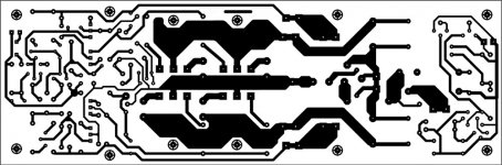
Attachments
So did anyone tried to make -quasi amplifier with irfp240 mosfer
of couurce they have different characteristics but can we consider what would happend with the SOAR?
And other questions: are there some kind of computer programs that can CALCULATE everything with some kind of schematics: I mean you make schematics in this PC program and it calulates ewerything so you easy can CHANGE resitor values for BETTERand easyier modification of the amplifier?
AndrewT said:Hi Med,
did you download Bensen's spreadsheet as I suggested?
Did you read ESP as I suggested?
Did you read the SOAR link as I suggested?
When you can say yes to any of these, then come back.
You mean I shoold try search this sheet here on the search options: I tried already and didnt find anthing ill try google now
I found only this:
http://www.diyaudio.com/forums/showthread.php?s=&threadid=70523&highlight=Bensen+spreadsheet
Hi Med,
I seem to have got the line open.
Yes, that post and the thread refers to Bensen's spreadsheet, but not that link.
Email me and I will send you a copy of Bensen's original plus my modified version showing either FETs or BJTs, I guess you would want the FET version.
BUT
what is really important is that you download the link that describes the complete manual calculation and read it thoroughly to understand what the spreadsheet is doing for you. Remember computers are tools, YOU have to understand the process.
Go and read ESP. He has lots of good info on output stages and SOA and reactive loads.
Similarly read Leach. His design method is excellent, and some might say the amplifier resulting from his method is excellent as well.
post 3 has a link that connects http://www.diyaudio.com/forums/showthread.php?s=&threadid=57446
AndrewT said:Hi Med,
I seem to have got the line open.
Yes, that post and the thread refers to Bensen's spreadsheet, but not that link.
Email me and I will send you a copy of Bensen's original plus my modified version showing either FETs or BJTs, I guess you would want the FET version.
BUT
what is really important is that you download the link that describes the complete manual calculation and read it thoroughly to understand what the spreadsheet is doing for you. Remember computers are tools, YOU have to understand the process.
Go and read ESP. He has lots of good info on output stages and SOA and reactive loads.
Similarly read Leach. His design method is excellent, and some might say the amplifier resulting from his method is excellent as well.
sorry but I have some problems with finding links :
mail :
velikigrizli@gmail.com
So if it is not too much trouble to post all that on the mail if you have it on your PC
Thanks
ESP: sound westhost: yes I read some of articles there before: but author is not very much mosfet "orintated"... but there are agood articles I read it thoroughly
Re: Re: Re[02]: hi
LOL it's not just me that's noticed that then.
TomWaits said:Good to see you are still on top of the 500 word essay.
LOL it's not just me that's noticed that then.
Hi John (Keypunch) nice to see you back, and good to see that your keyboard skills are back too. I hope everything is going ok at your end.
As you see the thread is still going and I suspect the number of modules built might be around 100 (info gathered here and by email).
Anyway I'm sure there's plenty of room on this server for your input and commentry. Look forward to some more.
Hi Medogrizli,
I don't know if there are computer programmes that can calculate absolutely everything for you for any schematic. Generally you have to design something and then run a simulation. Nothing though can be done without some basic knowledge. I.e; ohms law, semiconductor knowledge, reactive components, electronics related formula and maths.
Considerations such as SOAR whilst very important have more to do with device selection (and numbers) rather than the basic knowledge electronics enthusiasts need. I hope I do not offend you, especially as I don't know the depth of your knowledge, I just want to express how important it is to fully understand the fundamentals.
Cheers
Q
5.1
Thank you all for your valuable comments .
I just dont know how to quote individual posts ,but all of you posts were very helpful and inspiring .
My plans are as follows .
I plan to use the 2 fet layout for the individual channels and the 5 pair layout for the subwoofer amp .
The voltages for the 5 channels would be 25-0-25 transformer and for the subwoofer it would be around 45-0-45 . I will be using an EI core trafo ,as toroids are hard to find here and I am very much excited to wait for a supplier to supply with me with a toroid after a week .
I just bought my heatsinks yesterday from a second hand store ,and the heatsinks in all weigh around 6 kgs .
I hate fans ,so I am planning to use bigger heatsinks .
I will be making my own pcbs for my project ,but I will be making them in excess . If any one is interested in the pcbs ,I can send them for free ,provided you pay up for the postage.. lol . The pcbs will be in glass with tinning and no solder masking .
I will be posting the pics by next week ,as I have the weekend for working on the pcbs and for buying the components .
Will keep you all posted on the developements .
cheers
Yug
Hi Quasi,
(another Adelaide DIYer here)
congratulations on your N channel designs both the MOS and BJT versions this is an excellent thread.
I am wondering what the maximum voltage supply rails you can use for your amplifier are specifically the N channel mosfet amp??
-Dan
(another Adelaide DIYer here)
congratulations on your N channel designs both the MOS and BJT versions this is an excellent thread.
I am wondering what the maximum voltage supply rails you can use for your amplifier are specifically the N channel mosfet amp??
-Dan
danieljw said:Hi Quasi,
(another Adelaide DIYer here)
congratulations on your N channel designs both the MOS and BJT versions this is an excellent thread.
I am wondering what the maximum voltage supply rails you can use for your amplifier are specifically the N channel mosfet amp??
-Dan
Why would you want to live anywhere else?
Please refer to the power selection table here http://www.diyaudio.com/forums/showthread.php?postid=794932#post794932. This shows the maximum voltage that can be used is 85 volts. Caution though if you do, the heatsinking for the MJE350/340's must be quite large as they dissipate a lot of heat. Sendus an email and I'll send you the latest documentation for the amp.
This other amp can be used with voltages up to 95v http://www.diyaudio.com/forums/showthread.php?postid=991050#post991050.
Cheers
Q
- Home
- Amplifiers
- Solid State
- Power amp under development