rlg_200 said:quasi & tomwaits,
can u post the technical data (specification) of ur amp.
damping factor=?
thd+n=?
input sensitivity=?
input impedance=?
ouput impedance=?
rlg.")
It is not possible to give specifications that are meaningful for the module alone. Specifications are so variable depending on many things outside the module, including power supply (size and quality), case wiring and actual components used. Remember this amp was designed to take whatever components constructors had access to depending on their circumstances.
I can only post what I achieved and unfortunately the capabilities of my amp exceed the measurement capability of my instruments but I'll give it a go.
For my fully completed amp;
THD = better than 0.01% at 1Khz at near full power.
Noise = better than 110dB (completely inaudible)
Input sensitivity = about 1.25v rms (for my amp*) for full power into 8 ohms
Output impedance = very low and depends on the FETs you use and source resistors you use. I have not measured this in my amp.
Damping factor = very high again depending on the FETs etc...I have not measured this for my amp but it would be at least 150.
I guess the proof is in the pudding...or listening. You should survey constructors of the amp in this thread to get an understanding about it's sonics.
*this depends on the gain configuration plus the power supply voltage and capability.
Cheers
Q
edl said:Hi,
I read back many pages of the thread, but I cannot find the latest versions schematic...
Shall somebody attach it, or give me a link...
Many thanks,
regards
Here's the latest schematic.
Cheers
Q
Attachments
technical data
Quasi,
first thank u quasi for ur reply.
yeah, ur right its hard to get the specification because of variable inside and outside of module. But according to ur specification, THD @ 0.01%, damping factor near @ 150dB. I think ur amp is great ur amp can compete the branded amp.
one question again did u try to connect ur amp into bridge mode. or is it possible to connect into bridge mode. Anway I'm just planning to build ur amp soon.
I have simple caculation ur amp to produce high power into bridge mode.
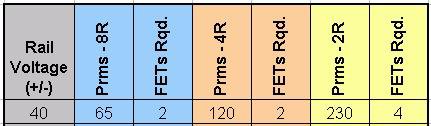
6 fet ouput @ 60 volt per rail
@ 16 ohms=300watts rms
@ 8 ohms=500watts rms
@ 4ohms = not reccomended possible thermal runaway
10 fet output @ 70 volt per rail
@ 16 ohms=500watts rms
@ 8 ohms=900watts rms
@ 4ohms = not reccomended possible thermal runaway
many thanks
rlg
Quasi,
first thank u quasi for ur reply.
yeah, ur right its hard to get the specification because of variable inside and outside of module. But according to ur specification, THD @ 0.01%, damping factor near @ 150dB. I think ur amp is great ur amp can compete the branded amp.
one question again did u try to connect ur amp into bridge mode. or is it possible to connect into bridge mode. Anway I'm just planning to build ur amp soon.
I have simple caculation ur amp to produce high power into bridge mode.
6 fet ouput @ 60 volt per rail
@ 16 ohms=300watts rms
@ 8 ohms=500watts rms
@ 4ohms = not reccomended possible thermal runaway
10 fet output @ 70 volt per rail
@ 16 ohms=500watts rms
@ 8 ohms=900watts rms
@ 4ohms = not reccomended possible thermal runaway
many thanks
rlg
Re: technical data
Hi rlg,
I think the Quasi amp can blow the doors off many brand name amplifiers. The key is your build quality! If you over build the power supply and select the finest components to stuff your boards, well you will know it when you hear it!
From being in the thread and on the DIY participating I figure this design should run on lower rails like +_45DC~50DC plus use a very large rectifier (40~50amp) and tones of Capacitance like 30-40,000 uF per rail. Put the 8 pairs of MOSFETs on the board and rock it! It may be suitable to bridge then?
One of the largest factors is the board itself; Q did not intend it for such use so it would be wise to etch a printed circuit board with such an application in mind. I think the output devices would end up on their own PCB with very thick traces to handle the high currents.
I hope that helps! Happy building!
Shawn.
BTW: Aside from being very powerful, my quasi amp has a very balanced sound. It is clear and vibrant. I have stopped using tone controls for the first time in my life when I hooked up my Quasi to my HiFi! I haven’t looked back since. This amplifier provides a very honest soundstage. With increasing listening time I find the Quasi amp slowly becoming a benchmark for sound.
  The second build, I posted on this thread and is currently under construction, will be pure art. It will surpass all Quasi's to date, I promise! Though it may take the entire winter to finish.
rlg_200 said:I think ur amp is great ur amp can compete the branded amp....
...I have simple caculation ur amp to produce high power into bridge mode.
6 fet ouput @ 60 volt per rail
@ 16 ohms=300watts rms
@ 8 ohms=500watts rms
@ 4ohms = not reccomended possible thermal runaway
10 fet output @ 70 volt per rail
@ 16 ohms=500watts rms
@ 8 ohms=900watts rms
@ 4ohms = not reccomended possible thermal runaway...
Hi rlg,
I think the Quasi amp can blow the doors off many brand name amplifiers. The key is your build quality! If you over build the power supply and select the finest components to stuff your boards, well you will know it when you hear it!
From being in the thread and on the DIY participating I figure this design should run on lower rails like +_45DC~50DC plus use a very large rectifier (40~50amp) and tones of Capacitance like 30-40,000 uF per rail. Put the 8 pairs of MOSFETs on the board and rock it! It may be suitable to bridge then?
One of the largest factors is the board itself; Q did not intend it for such use so it would be wise to etch a printed circuit board with such an application in mind. I think the output devices would end up on their own PCB with very thick traces to handle the high currents.
I hope that helps! Happy building!
Shawn.
BTW: Aside from being very powerful, my quasi amp has a very balanced sound. It is clear and vibrant. I have stopped using tone controls for the first time in my life when I hooked up my Quasi to my HiFi!
I haven’t looked back since. This amplifier provides a very honest soundstage. With increasing listening time I find the Quasi amp slowly becoming a benchmark for sound. The second build, I posted on this thread and is currently under construction, will be pure art. It will surpass all Quasi's to date, I promise! Though it may take the entire winter to finish.NIce shawn..
My Quasi is still under construction, I need more time to finish , then Ill post an update , Im planning to construct the High Power Quasi Amp too (the one that can drive large speaker array for Mobile sound systems) as soon as a finish with the 6 Fet version, Shawn please do post some picture of your 2nd Quasi module just to inspire us Quasi builder here as soon as you start with it.. Good luck Shawn.
joel
Re: NIce shawn..
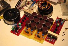
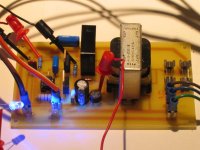
It has been posted a few pages back but here it is:
Supply voltage +_40V DC
One toroidal per channel each rated 30-0-30VAC @ 400VA
jhoel47 said:... Shawn please do post some picture of your 2nd Quasi module just to inspire us Quasi builder here as soon as you start with it.. Good luck Shawn.
joel
It has been posted a few pages back but here it is:
Supply voltage +_40V DC
One toroidal per channel each rated 30-0-30VAC @ 400VA
Attachments
Hi Tomwaits,
30mF to 40mF is just about right if you follow the general recommendation of +-2mF to +-3mF per Apeak of output.
For a 4ohm load +-30mF can drive to a maximum of 15Apk and 60Vpk which equates to 450W into 4r.
However if you want to ensure stabilty between the various LF time constants built into the amplifier and PSU then often the PSU needs even more capacitance if the amp is designed to run flat down to 1Hz or 2Hz.
I have recommended 160mS to 200mS in the past.
8ohm +-20mF to +-25mF or 4ohm and +-40mF to +-50mF can achieve these low frequency time constants.
To bridge or not to bridge...that is the question....
Hi rlg_200
I have not tried the amp module in bridge mode however I see no reason why it could not be done. Of course you will need a phase inverter and know how to connect it all up.
Everyone seems to be seeking more power from this module and while that's ok, it's supposed to be a high quality audio power amp.
If you do bridge it please post your work. I as I'm sure others would be very interested.
Cheers
Q
Re: Hi Mr TOM W.
I wonder where I got that idea? Kind of a tribute!
Shawn
zeonrider said:Nice PCBs ofcourse look on to page26.
Something look the same.
Regards zeoN_Rider
I wonder where I got that idea? Kind of a tribute!
Shawn
AndrewT said:Hi Tomwaits,I have recommended 160mS to 200mS in the past.
8ohm +-20mF to +-25mF or 4ohm and +-40mF to +-50mF can achieve these low frequency time constants.
Dude! You need an avatar image, it should be a huge pic of some wicked power supply!
Shawn.
Hi Tomwaits,
these suggestions are not huge, I consider them to be normal for good to excellent low frequency response.
eg. +-20mF allow power output upto 180W (+-3mF/Apk)
and +-25mF goes to 270W. These are the target range that this quasi is designed for.
If you want good accurate bass I believe it can only be achieved if the amp does not wilt when asked to produce high levels of continuous low frequencies. I use the further rule that the input high pass filter be selected to be no lower than one octave above the PSU i.e. 80mS. This gives 4Hz @ -1db. 2Hz @-3db if the rest of the amplifier is designed to complement these performance parameters.
If you use the +-2mF/Apk rule then you can squeeze more power out of these smoothing caps, at the expense of more modulation of the power rails.

- Home
- Amplifiers
- Solid State
- Power amp under development