Re: Toroids VA Capability
Quasi,
Thanks for your reply.
Somehow I hve to find out what the math in behind the figures you give me for some source or maybe you one day. I will then add the math to a master spreadsheet I have to keep all the calculations in and auto calculate as I work with the different design variables.
I had a hunch 4 mondules woudl be ok, as I was extrapolating from your use of 500VA for two modules at a high power level. Even though 44-0-44V can result in about 160-170W per module of power (I assume 8 ohms) I really expect to need about 1-5 watts most of time for the usual listening I do. even with loud listening I really do not expect to need more than 20-25 watts of power. These toroids were available at good price so I thought for some amplifiers I like to use them. At least I have reasonable dynamic headroom up to 160+ watts which is more than good safety margin for my needs. Even though I do not expect to drive amps hard, I will limit to 4 modules/960+VA toroid. I have one rated at 1120VA that is 44-0-44V.
My intent for PSU circuit is to have a PSU circuit per module. Each PSU circuit module will have a bridge rectifier for each side of the amp rail, and of course dedicated filter caps that go along with that. I was thinking I would have two or three 10,000uF or so filtering caps per each side of a rail.
I suspect for this sort of 4 module configuration I need to have the soft start circuit delay set to about 5 seconds or more to be on safe side. These 44-0-44V toroids also have a seperate 12V output winding that should be most useful for a soft start circuit.
On the T8 question I will do some hunting about for possible candidates. Thanks for your reply. In my newness to all this design stuff I asked as I was not sure if there was specific characteristics I had to be aware of for choosing an alternate to T8 being a BC546. The question was for sure related to ensure T8 is on the heatsink secure. I suspect I will place T8 on top of one of the output devices monted on the heatsink. I still sorting out comments from various sources respecting the pros and cons of a T8 like device being just on the heatsink close to the output devices or mounted atop one of the output devices.
Regards,
John L. Males
Willowdale, Ontario
Canada
14 December 2005 09:45
Hi Keypunch,
The secondary output of the transformer when fed with nominal mains voltage is directly related to the manufacturer's specified output voltage.
When fully loaded to max VA rating the output voltage = Vac
Vdc = {square root (2) * Vdc } -{diode drop}
e.g. 500VA 44Vac gives Vdc when pushing out 8.04A is = 44*1.414 - 1.4 = 60.8Vdc
When the amp is idling and putting out very low quiescent current the output voltage rises by the regulation percentage. Output voltage =Vac*1+regulation.
Vdc= {square root (2) * Vdc }*{1+reg} -{diode drop adjusted}
eg {44*1.414}*{1+.06}-0.8=65.16Vdc.
These voltages will be slightly different when you use a rectifier capacitor smoothing bank due to high peak currents and I squared R losses but accuracy is usually good enough.
If the mains supply is running high all these voltages increase. In the UK this can be +6%-10% but our figures are fugded to make it look as though we comply with the European 220Vac when we are still running on 240Vac supplies.
Apply a factor for your supplier at the quiescent voltage and you could be running as high as 69Vdc. This demands 75V or 80V capacitors. Most caps will take a short term overload but I would not recommend you use this allowance for supply voltage variation.
Hi Andrew,
Thanks for the info on the transformer secondary output voltage, math and reminding me of the rated vs actual mains voltages. I measured these toroids about year ago and though rated at 44-0-44V, with the AC voltage here generally 125 the secondary was actually close to 47-0-47V. I will have to add that element into the spreadsheet calculations as pointed out by way of your comments.
I have no intents to run any capacitors too close to rating. There is some suggestion one should run the filter capacitors about 80% of rated working voltage for best performance of the capacitor. I have not done enough research yet to validate if this is fact or myth. I would tend to lean towards as best I can afford working voltage rating at least 40% above the circuit demands.
I have now learned the filter capacitors have to be the working DCV out of retified DC, ignoring any voltage drops the output MOSFETs will see.
Thanks for the insight to the 12V winding on the toroid that has the soft start on it. An obvious poitn you have pointed out that I failed to consider. I guess this is why so often people use a seperate transformer for the soft start circuit. I have to evaluate the softstart side to avoid case of amp never reallly starts as not enough voltage gets to sodt start circuit to enable soft start to disengage. Guess this is like being caught between a rock and hard place suitaton! If cannot avoid that condition then alternate solutions will be in order.
Regards,
John L. Males
Willowdale, Ontario
Canada
14 December 2005 14:11
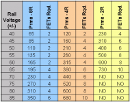
The following table can be used as a guide when trying to determine output configurations for the amp module. It provides recommendations for FETs per amp module (not FETs per rail).
I have based the table on typical IRFPXXX FETs rated at 180 watts (Tc = 25 degC), derated for a Tc of 50 degC. Naturally more / less FETs can be used if they are weaker / stronger.
The table does assume a virtual limitless power supply so actual power acheivements will probably be less.
The table does not remove the need to fully understand the workings of the 3 other main parts of the schematic as there are some voltages that need to maintained irrespective of the supply rails.
Let me know if parts of the cct aren't clear.
Cheers
Attachments
Power loss
Hi Quasi,
I finished my first amp module with 2 fets (IRFP450) and +/- 45V supply (just for testing before I put all 6 with +/- 70V).
I'm confused because I can only get about 30W of power in 8 ohm speaker (by ear) and according to your tabel I should get about 85W.
What could be the problem of this power loss.
I also use BF420 (si-N 300V 0.1A 0.83W) instead 2sc1845 transistors. Could this can be the problem and if so please advice me what replace could I use.
Thanks in advance!!!
Pejin Miodrag
I'm confused because I can only get about 30W of power in 8 ohm speaker (by ear) and according to your tabel I should get about 85W.
Your ear knows the 30W reference?! It's impossible to decide that an amp gives you 30W or 85W power when listaning to music... Anyway 85W is the RMS power. The music power, and others are much different... You aren't listening to a sine wave...
So if everything seems to be OK (no DC on output, etc...), your amp will gives out the 85W RMS to 8ohms with +/-45V. Don't belive your ears
")
Hi Edl,
this must be the only time I could possibly agree with your statement
Normally, I would say do believe your ears.
this must be the only time I could possibly agree with your statement
Don't believe your ears
Normally, I would say do believe your ears.
Dear AndrewT,
Thanks.
Yes, I say, let's belive your ears, too. I say: only belive your ears!
With my last sentence: "Don't belive your ears" I wanted to say that don't belive your ears in power-measurement. Sorry, I was so ambiguous (dubious)... The reason is my poor english.
This must be the only time I could possibly agree with your statement.
Thanks.
Normally, I would say do believe your ears.
Yes, I say, let's belive your ears, too. I say: only belive your ears!
With my last sentence: "Don't belive your ears" I wanted to say that don't belive your ears in power-measurement. Sorry, I was so ambiguous (dubious)... The reason is my poor english.
My Ears!?
The expression was wrong (because my english is not very good). I just want to say that this amp is giving the same "loudnes" as my 25W (that I know for sure) integrate amp on the same speaker in the same room so, I thought there is probably something wrong!?
My apologys for misunderstanding.

The expression was wrong (because my english is not very good). I just want to say that this amp is giving the same "loudnes" as my 25W (that I know for sure) integrate amp on the same speaker in the same room so, I thought there is probably something wrong!?
My apologys for misunderstanding.
Hi Pejinm,
I think you could hear a slight difference between 25 & 80 watts, just over 3 dB.
It is not easy to assess your situation because your other amp can sound louder depending on several possibilities.
- power supply size, how big is it on the quasi amp?
- tone control settings
- clipping (the ear may not hear slight clipping)
- your other amp is a NAD or similar (power envelope capability).
- the quasi amp isn't being fully driven (gain issue).
The way to check power delivery is to run the amp with sine wave input into a dummy load and then measure the voltage swing.
The table is a guide only. My amp uses +/- 73v rails (idle) and I achieved 210 watts RMS (single channel driven) into 8 ohms and 360 watts into 4. The transfomer is a 500va toroid.
The BF470 is not an ideal transistor for this stage, so for 45v rails try changing it to a BC546 (watch the pin-outs). Also with 45v supply you need to change R6 to 12K otherwise the constant current source (T4) will not work properly.
Cheers & good luck.
Sorry Pejinm,
I forgot to add;
When you upgrade your power supply please make sure it is something similar to what I constructed. When you do let me assure you that you will have a very powerful and clean amplifier that will sound very different to a 25 watt unit. Whilst an improvement of 9dB will be very noticeable, what you will appreciate is the ability of the amp to deliver lots of current that you will hear as strong controlled bass and clear mid-highs.
I recently ran my amp and a friends NAD receiver into his IMF speakers. Whilst the NAD sounded great, my friend has started building....and the NAD will become a pre-amp.
Cheers
The "Table"
Hi Quasi,
A few quick questions about your table (Yes I can ask a "few") :
1) "Rail Voltage (+/-)" is inclusive of rectifier loss, choke if used and filter capacitor, but exclusive of FET output devices and PSU rail voltage measured under no load?
2) How you measure or determine from Specs loss a FET output device will incur?
3) What linear derate rate did you assume for Tc of 50C (from the usual spec'ed Tc reference of Tc 25C)?
Regards,
John L. Males
21 December 2005 08:09
Willowdale, Ontario
Canada
P.S. Have a Happy Holiday Season. jlm
Hi Quasi,
A few quick questions about your table (Yes I can ask a "few")
:1) "Rail Voltage (+/-)" is inclusive of rectifier loss, choke if used and filter capacitor, but exclusive of FET output devices and PSU rail voltage measured under no load?
2) How you measure or determine from Specs loss a FET output device will incur?
3) What linear derate rate did you assume for Tc of 50C (from the usual spec'ed Tc reference of Tc 25C)?
Regards,
John L. Males
21 December 2005 08:09
Willowdale, Ontario
Canada
P.S. Have a Happy Holiday Season. jlm
I'll throw in my two pence worth as I think it will be along the same lines as Quasi
The rail voltage is the DC voltage as seen by the amp when under load. You wouldn't use a choke on a class-b amp due to the current waveform being very dynamic compared to class-a.
Determining MOSFET losses is not really all that easy from specs and I tend to make an informed guess based on experience and tests. It is dependent on the gate-source voltage, transconductance, and on-resistance.
The derating curve can usually be found in the MOSFET data sheet.
Hi John,
For the DC rails I used a theoretical power supply that would sustain its full power voltage to within 5% of the float voltage. I then determined a FET loss from graphs published by IR and varied those to a degree dependant on the amp load. These are drawn in the IR graphs as gate voltage v current. Then I added a little bit for the on resistance of the FET. Finally I factored these losses when determining the available voltage to the speaker. So it is after the rectifiers and does not consider rectifier loss.
IR publishes the SOAR for devices at 25 degC in a chart and also a derating curve (power diss v temp) in another. I used the 10 mSec SOAR curve.
At 50 degC I determined that a typical IR FET could dissipate approx 85% of the rated 25degC rating. So I derated the SOAR curve accordingly. I did this to allow for warm heatsinks.
Then I used the data in MS Excel to draw a SOAR v load graph for each output configuration (example attached). Provided the SOAR curve does not cross the load curve the output stage should survive.
The SOAR v load chart posted below shows the situation with 4 FETs using 60 volt rails. As you can see the 10 mSec curve in red is just above the 4 ohm load curve (reactive) but well inside the 2 ohm curve.
Cheers
Just saw richie00boy's reply....what he said too.
Cheers again.
Attachments
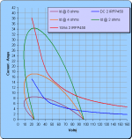
Note the load curves posted above assume a worst case scenario of current and voltage being 45 degrees out of phase in a reactive load i.e. a speaker system. This extreme may never happen at any real power level but with electronics ya gotta assume the worse.
I had a look inside my recently purchased (proud smile) Yamaha RX777 receiver and there is no way that Yamaha have taken as robust approach as I have.
Cheers
I had a look inside my recently purchased (proud smile) Yamaha RX777 receiver and there is no way that Yamaha have taken as robust approach as I have.
Cheers
Re: The Table
Gentlemen, no hurry for reply, I am happy to wait unitl the the holiday season activities you have areover with.
Hi Richie,
Thanks for your comments. I only referenced the choke to clarify the PSU system area for a more general view. Understand your points about MOSFET losses. My one question would be for a given built MOSFET amp can one measure the MOSFET losses directly or is it a case of indirect calculations to aproximate what the MOSFET losses were based on some direct measurements?
Hi Quasi,
Thanks for your reply and the sample spreadsheet curve example you posted. I have to say I am far form as versed as you are in all these details. Frankly I have never quite understood some of the curves on the MOSFET datasheets, and one of those was related to SOAR.
Let me distill how I calculate SOAR based on my understanding form reading many postings related to SOAR as best I understand SOAR thus far. Via a spreadsheet I created I calculate for the design Tc (which of course if the max design Tc) and calculate Pd using the spec derate factor. Based on all of MOSFET specs I have reviewed Id is specified for 25C and 100C, but there is not a specified Id derate factor. What I do instead is take the Id Tc for 25C and 100C, create an Id derate factor and then calculate the Id for the design Tc in similar manner to calculating the design Pd. Of course for same Tc. I then do the PSU calculations for the design output power of the amp which takes into account rectifier losses, estimated MOSFET losses and a generic loss in PSU rails. Then I apply a calculation of the PSU current demand based on the minimum speaker impedance to determine current demands the output device(s) would be required to handle. From there with MOSFET spec data that has been entered in the spreadsheet the spreadsheet weeds out those MOSFETs that cannot meet the Vdss+safety margin entered in spreadsheet. Then the spreadsheet determines based on Id and Pd how many devices are required to meet the designed output power at the minimum impedance of the design.
Would you feel that effectively I have at least have done what you have done to determine the SOAR of a output device for a given design output power of an amp? I know I am assuming a straight line for Id derate which it not actually the case, but for the Tc's I will ever design for I have found that the Id derate I have chosen to interpolate is actually a higher derate fator that the curves on the graph if Id vs Tc indicates for the many MOSFET datasheets I have reviwed. I have also compared the rsults agains many different amp designs and so far it appears the spreadsheet calculations at least close or if not clise at least err on the safe side of the designs I have compared to. Please realize unlike you quasi, I do not make any calculations based on transient signal demands. By in large I do the calculations for RMS and and for P-P try, not must, to ensure the design meets within the RMS state of the output device specs for P-P of the expected output signal. Any P-P that is outside the RMS spec of the device I evaluate on a case by case basis manually for now.
Now I do a pile of other secondary calculations that have no bearing on the power demands of the output drivers using the specs from the datasheets to determine suitability of a output driver based on a number of other criteria I deem important to a design. The spreadsheet also does a set of calculations for other PSU design factors like VA rating of secondary, required secondary voltage, filter capacitor sizing, etc. Suffice to say the spreadshhet can drive me wild, not just due to extent of calcualtions to be done, but to have flavours based on some very different opinions that exist on some of the most basic design calculations. I have no less than three sets of PSU design calculations. For the SOAR based calcualtions I base the rail voltage calcualtions on what is needed. The PSU sheets deal with being able to deliver the rail voltages for the SOAR calculations.
Regards,
John L. Males
22 December 2005 07:32
Willowdale, Ontario
Canada
- Home
- Amplifiers
- Solid State
- Power amp under development