Re: PICTURE
Very nice. Well done.
Elso's concerns about the drivers heatsink is valid. It looks too small to stop them getting too hot. Attached is a photo detailing the heatsink I used, I think even mine is too small (heatsink that is) so I'm using a case fan to extract the warm air.
Mounting the FETs can be a little tricky, let me know if you have problems.
If you turn one bank of the 5 watt resistors around they will fit better.
Your work is very good....I love the red...
zeonrider said:Of course in FERRARI RED
Very nice. Well done.
Elso's concerns about the drivers heatsink is valid. It looks too small to stop them getting too hot. Attached is a photo detailing the heatsink I used, I think even mine is too small (heatsink that is) so I'm using a case fan to extract the warm air.
Mounting the FETs can be a little tricky, let me know if you have problems.
If you turn one bank of the 5 watt resistors around they will fit better.
Your work is very good....I love the red...
Attachments
Update & correction
The capacitor shown in the PCB layout across the c-e of T8 should stay. It was omitted in the schemtic in error and has a value of 100nF. I'll post the corrected schematic soon. It is easily retrofitted if anyone has left it out.
John you beat me to it with your 8 FET board. I have had some emails asking for a higher power version and last night I finished a 10 FET layout (attached). I will shortly post a table that will dimension power capabilities for a range of rail voltages, load impedances and FET count.
This project seems to be gaining popularity, I hope to see some finished project photos posted soon.
Cheers
Attachments
Re: OPINION
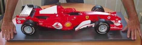
Nice car .....married AND can afford a Ferrari.....whoa
zeonrider said:THANKS for your opinion , I,ll make new. But leave amps. for a little. Look this: scale 1:6 diecast zink aloy, with soft tires, price hmmm, around 3600 Euro.
Nice car .....married AND can afford a Ferrari.....whoa
Re: Update & correction
Hi quasi,
Good I caught the capacitor about T8. I looked at the prior board designs you posted before putting stake in ground to start building. I know there was much to do in comments made to remove these (miller I think they are called) capacitors. I found at least one other that semed to be removed, so I thought maybe this was removed as well seeeing as no vaule/reference was made, but not worth making a new board in case a suitation arose that this optionally could be put in form example. See what days of board editing can turn up!")
Funny you mention the 5 output device pair and making a design per the request. I actually thought of making a 5 or 6 pair design for those that love to have "power", but thought that the 4 pair was more than enough. I also know there is a limit to teh power or voltage rails a design can be used with, and I did not want to encourage with ease those not willing to ask or make effort to edit the board image for more output devices. Also some of us, like me , like to have good safety margins or lower operating temperatures of the output devices. With that in mind even though the PSU design would not allow for more than 100 - 150W for a give PSU I chose to limit to 4 pairs. The initial edits I made few days ago and in summer were all for 1 and 2 output pair(s) devices as I have some nice APT MOSFETs that can handle alot more power than an IRFP450, and I still want to make some single output pair versions for low power use even though you say there are "more efficient" designs for low power.
I like to ask you how easy it is for you to create using your 3 pair T-247 device design to a 3 pair T-220 device. I do have a need for a T-220 based device. Initially I was just going to use the current board layout and do a quickie edit to bring in the lead holes for T-220. That edit is only a few minutes. The adjust the mount hole and trace I suspect would take me a hour or so each device and I may not do for a couple reasons. I was going to use a different mounting orientation to see how well it would work to give more output device surface area to bleed the device heat away from the output device. That in itself make the output device mounting hole and surrounding trace an non-issue. The much more time consuming edit I woudl face is to close up the T-247 spacing for a T-220 spacing so I could have say 5 pairs of T-220 output devices in the same board space as 3 or 4 T-247 output devices.
I have no idea how much time it takes you to redo just the output device area to change from T-247 to T-220 form factor. If not alot of time, if you do decide to make a T-220 form factor varient, a T-220 of 5 output pair version you just created would be great. If it means alot more time doing a 5 vs 3 output pair in the T-220 form factor, then I will make the 5 output pair version as well as I will be happy to make the 4, 3, 2 and 1 output pair(s) versions using GIMP.
Regards,
John L. Males
Willowdale, Ontario
Canada
12 December 2005 09:22
quasi said:The capacitor shown in the PCB layout across the c-e of T8 should stay. It was omitted in the schemtic in error and has a value of 100nF. I'll post the corrected schematic soon. It is easily retrofitted if anyone has left it out.
John you beat me to it with your 8 FET board. I have had some emails asking for a higher power version and last night I finished a 10 FET layout (attached). I will shortly post a table that will dimension power capabilities for a range of rail voltages, load impedances and FET count.
This project seems to be gaining popularity, I hope to see some finished project photos posted soon.
Cheers
Hi quasi,
Good I caught the capacitor about T8. I looked at the prior board designs you posted before putting stake in ground to start building. I know there was much to do in comments made to remove these (miller I think they are called) capacitors. I found at least one other that semed to be removed, so I thought maybe this was removed as well seeeing as no vaule/reference was made, but not worth making a new board in case a suitation arose that this optionally could be put in form example. See what days of board editing can turn up!
Funny you mention the 5 output device pair and making a design per the request. I actually thought of making a 5 or 6 pair design for those that love to have "power", but thought that the 4 pair was more than enough. I also know there is a limit to teh power or voltage rails a design can be used with, and I did not want to encourage with ease those not willing to ask or make effort to edit the board image for more output devices. Also some of us, like me
, like to have good safety margins or lower operating temperatures of the output devices. With that in mind even though the PSU design would not allow for more than 100 - 150W for a give PSU I chose to limit to 4 pairs. The initial edits I made few days ago and in summer were all for 1 and 2 output pair(s) devices as I have some nice APT MOSFETs that can handle alot more power than an IRFP450, and I still want to make some single output pair versions for low power use even though you say there are "more efficient" designs for low power.I like to ask you how easy it is for you to create using your 3 pair T-247 device design to a 3 pair T-220 device. I do have a need for a T-220 based device. Initially I was just going to use the current board layout and do a quickie edit to bring in the lead holes for T-220. That edit is only a few minutes. The adjust the mount hole and trace I suspect would take me a hour or so each device and I may not do for a couple reasons. I was going to use a different mounting orientation to see how well it would work to give more output device surface area to bleed the device heat away from the output device. That in itself make the output device mounting hole and surrounding trace an non-issue. The much more time consuming edit I woudl face is to close up the T-247 spacing for a T-220 spacing so I could have say 5 pairs of T-220 output devices in the same board space as 3 or 4 T-247 output devices.
I have no idea how much time it takes you to redo just the output device area to change from T-247 to T-220 form factor. If not alot of time, if you do decide to make a T-220 form factor varient, a T-220 of 5 output pair version you just created would be great. If it means alot more time doing a 5 vs 3 output pair in the T-220 form factor, then I will make the 5 output pair version as well as I will be happy to make the 4, 3, 2 and 1 output pair(s) versions using GIMP.
Regards,
John L. Males
Willowdale, Ontario
Canada
12 December 2005 09:22
Hey John,
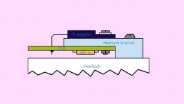
The board was designed specifically to use TO247's because they are also used as the spacers that keep the board off the heatsink. Using TO220's can be done with this board with the addition of a heatsink bracket. The TO220 FETs would then mount on top of the PCB and on the bracket (see rough drawing).
The 27 ohm gate resistors then have to mount under the PCB.
It would not be difficult to convert this board for TO220s along the lines I described above. It would shorten the length of the board.
It gets back to available time I guess, maybe over the next week or so I'll post one.
Available time; 24 hours - ((work & sleep) / (kids & spouse)) = own time (not much).
The request from other hobbyists (via email) have mainly been about driving into 2 ohm loads, hence the 10 FET board. I still need to post the "safe power chart".
Cheers
Attachments
TO-220 Variant
TO-220 Variant
Hi Quasi,
umm, ok thanks for the reply and the mounting image to put a picture to what you described for a TO-220 version of the board. I was not envisioning something quite as complex to effect the TO-220 mounting. What I was going to do was mount the TO-220's on the trace side of the board as the TO-247's, but not parallel to the PCB, but at right angles like a T type mount. In fact I am likely to mount the TO-247 output driver version in same T-mount configuration. This would keep everything the same, including the gate resistors mounted on the component side as the current PCB design has.
Can you advise me if it is less time to make a TO-220 5 output device pairs version by simply changing the PCB as it currently is to TO-220 devices and spacing change of the output devices leaving all else the same? I will be more than happy to then created the 4,3,2, and 1 output pair versions of the PCB using GIMP. I am hoping it will take less time for you if all you need to do is just respace the existing PCB board design and in my opinion actually allows for a less complicated heatsink mounting solution. Your thoughts?
In terms of the quasi time equation, suffice to say you seem to manage well with your time. As to a timeline for a TO-220 PCB version, I am in no hurry. You can certainly leave creating such a variant until the new year. I am fine with the TO-247 versions and variants I have created. They will allow me to dabble and test some things out before deciding on final output driver use and other variations or part types I want to test out.
Oh I have another question. lol lol lol Do I ask questions? lol lol lol .... T8 (BC546) is a TO-92 form factor. I have a preference for a flat like form factor like a TO-126 or similar flat like form factor with hole for a T8 like device. Any alternate suggestions without worry if pinout is different or is the a very specific reason (other than quasi had lots of these lying about) you chose BC546 for T8? I can deal with the minor matter of different pinout for a different device.
I had a feeling the requests for more output devices was for more output power. I had no idea there are that many difficult loads down to 2 ohms about. I guess the reactance is playing into this more than I assumed or that my humble playing levels use Then again maybe the lower dips are complicated by passive crossover networks?
Any of those in need for 500W into 2 ohms users care to comment/share more about there need for 500W into 2 ohms? I am interested to know as I had been doing calculations of amplifier power handling ability based on 3 ohms for non-tweeters drivers, and 2 ohms for tweeter drivers. For a general use amp driving a passive crossover I will be more than fine with what I build for the less than moderate demands such suitations have.
Regards,
John L. Males
Willowdale, Ontario
Canada
13 December 2005 09:52
TO-220 Variant
Hi Quasi,
umm, ok thanks for the reply and the mounting image to put a picture to what you described for a TO-220 version of the board. I was not envisioning something quite as complex to effect the TO-220 mounting. What I was going to do was mount the TO-220's on the trace side of the board as the TO-247's, but not parallel to the PCB, but at right angles like a T type mount. In fact I am likely to mount the TO-247 output driver version in same T-mount configuration. This would keep everything the same, including the gate resistors mounted on the component side as the current PCB design has.
Can you advise me if it is less time to make a TO-220 5 output device pairs version by simply changing the PCB as it currently is to TO-220 devices and spacing change of the output devices leaving all else the same? I will be more than happy to then created the 4,3,2, and 1 output pair versions of the PCB using GIMP. I am hoping it will take less time for you if all you need to do is just respace the existing PCB board design and in my opinion actually allows for a less complicated heatsink mounting solution. Your thoughts?
In terms of the quasi time equation, suffice to say you seem to manage well with your time. As to a timeline for a TO-220 PCB version, I am in no hurry. You can certainly leave creating such a variant until the new year. I am fine with the TO-247 versions and variants I have created. They will allow me to dabble and test some things out before deciding on final output driver use and other variations or part types I want to test out.
Oh I have another question. lol lol lol Do I ask questions? lol lol lol .... T8 (BC546) is a TO-92 form factor. I have a preference for a flat like form factor like a TO-126 or similar flat like form factor with hole for a T8 like device. Any alternate suggestions without worry if pinout is different or is the a very specific reason (other than quasi had lots of these lying about) you chose BC546 for T8? I can deal with the minor matter of different pinout for a different device.
I had a feeling the requests for more output devices was for more output power. I had no idea there are that many difficult loads down to 2 ohms about. I guess the reactance is playing into this more than I assumed or that my humble playing levels use
Then again maybe the lower dips are complicated by passive crossover networks?Any of those in need for 500W into 2 ohms users care to comment/share more about there need for 500W into 2 ohms? I am interested to know as I had been doing calculations of amplifier power handling ability based on 3 ohms for non-tweeters drivers, and 2 ohms for tweeter drivers. For a general use amp driving a passive crossover I will be more than fine with what I build for the less than moderate demands such suitations have.
Regards,
John L. Males
Willowdale, Ontario
Canada
13 December 2005 09:52
My Amp's Pics
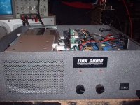
Wow!! This forum has grown a lot...
Congratulations to everybody who made it, hope yours sounds as good as mine do.
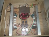
I wanted to show you some pics of mine almost completed.
I run out of $$ for the case, so I had to use what I had available, my case is made of 8mm wood, and will have it painted black sooner (or later )
)
If I have some extra $$, I'll buy a metal case to put it in, right now is working very good, no overheating and no distortion.
Pic 1...
Wow!! This forum has grown a lot...
Congratulations to everybody who made it, hope yours sounds as good as mine do.
I wanted to show you some pics of mine almost completed.
I run out of $$ for the case, so I had to use what I had available, my case is made of 8mm wood, and will have it painted black sooner (or later
)If I have some extra $$, I'll buy a metal case to put it in, right now is working very good, no overheating and no distortion.
Pic 1...
Attachments
can i use my 65-0-65 Vac 15kgs. transformer for the 5pair posted a while ago ~93Vdc ? what parts do i have to change ?
Can anyone honestly compare the super leach and this amp ?
Any comment on the super leach for mid's and highs while this amp for bass and mid-bass ?
I'm for outdoor PA
Can anyone honestly compare the super leach and this amp ?
Any comment on the super leach for mid's and highs while this amp for bass and mid-bass ?
I'm for outdoor PA
Hi! Quasi
Can I answered in your name. Thanks.
The amp. is real DIY, LUIGY, like whole life.(DIY), But main heatsink
fins must turn 90 deg.(up).second : imgine only one spark inside of amp, what will hapened with case? because made of wood.
Rolanddong:Yes 65-0-65 will be fine (about 2x90V DC ), dont forget beter cooling.I post first version of Leach Amp from 1980. I compare the sound with CREST, CROWN, PEAVY, PHONIC.Every of
this four amps has good power, but sound ,in my opinion is wery poor.Yes,LEACH.
Re: My Amp's Pics
Hi Luigi,
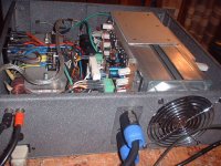
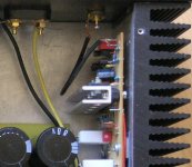
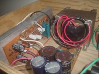
It looks from the picture of this post that you are only using 2 pairs of output devices? True? If so did you still use the IRFP450's or something different? Looks like you power supply is using a pair of Nippon Chemi-Con 10,000uF 63V capacitors each side of rail? True? I like to know as I have the same or very similar here (10,000uf 63V 105C), and access to more at good price I thought be good for medium power versions. What is the VA rating and secondary voltage of the transformer you are using? Like quasi I would like to know as well?
I suspect like you I will want to build one of the same power level as you have. I suspect I will select some choice TO-220 output devices I feel may be more suitable to my target for some verions of the amplifier I want to build. Some may be one or two output device pair(s) and some will be three or four output device pairs, no matter if I use TO-220 or TO-247 type output devices. Hence my interest in if you did make a two output device pair for your needs.
Shame my internet connection was not working for few months while my phone line was dead. Maybe you would of liked to use the 2 output pair variant PCB images of the boards without DC Detect I made from quasi's amplifier only board. I have not had chance to post these amplifier only boards yet as I need to get those files from a different system of mine. At least the 2 output pair version with DC Detection is available from free site page I put up a few days ago. ***** See quasi, I was not the only one having notions of a lower power version of you design
Hope you find the extra $$ to add in the other protection circuits and to place the ampl in a metal case Luigi. Great you have a working amplifier that you are happy with.
Regards,
John L. Males
Willowdale, Ontario
Canada
14 December 2005 06:46
LuigiDJ said:Pic 2...
Coming soon, DC protection and delay circuit, termal sensing and fan, clip indicator and some other gadgets that comes to mind.
Happy listening !!
Hi Luigi,
It looks from the picture of this post that you are only using 2 pairs of output devices? True? If so did you still use the IRFP450's or something different? Looks like you power supply is using a pair of Nippon Chemi-Con 10,000uF 63V capacitors each side of rail? True? I like to know as I have the same or very similar here (10,000uf 63V 105C), and access to more at good price I thought be good for medium power versions. What is the VA rating and secondary voltage of the transformer you are using? Like quasi I would like to know as well?
I suspect like you I will want to build one of the same power level as you have. I suspect I will select some choice TO-220 output devices I feel may be more suitable to my target for some verions of the amplifier I want to build. Some may be one or two output device pair(s) and some will be three or four output device pairs, no matter if I use TO-220 or TO-247 type output devices. Hence my interest in if you did make a two output device pair for your needs.
Shame my internet connection was not working for few months while my phone line was dead. Maybe you would of liked to use the 2 output pair variant PCB images of the boards without DC Detect I made from quasi's amplifier only board. I have not had chance to post these amplifier only boards yet as I need to get those files from a different system of mine. At least the 2 output pair version with DC Detection is available from free site page I put up a few days ago. ***** See quasi, I was not the only one having notions of a lower power version of you design
Hope you find the extra $$ to add in the other protection circuits and to place the ampl in a metal case Luigi. Great you have a working amplifier that you are happy with.
Regards,
John L. Males
Willowdale, Ontario
Canada
14 December 2005 06:46
Hello rolandong,
As zeonrider suggested the only issue could be cooling especially for the 4 MJE340/350's. The heatsink for these will need to be fairly large as they will be dissipating a total of around 5 watts.
A 10 FET board will need around 175mA of bias current and this amounts almost 16 watts per heatsink at idle, so make sure your main heatsinks are large (larger than what I used).
The 27K resistor (R11) will also run very hot dissipating around 0.3 watts, so you may want to upgrade this to a 1 watt type.
Other than that things should be fine and you will have an amp that will deliver around 380 watts into 8 ohms and nearly 700 watts into 4 depending on the quality of the power supply.
Oh and upgrade the fuses to 10 amps.
Cheers
Re: Toroids VA Capability
44 0 44 volts AC will give about 60v DC (+/-) so I would use capacitors rated at 75v as a minimum. The 63v rating is too close for my comfort.
With rails of +/- 60v the amp modules will deliver around 170 watts into 8 ohms each. Assuming an overall efficiency of around 60% then 276 watts will be drawn from the power supply per module (at full power). Divide this by a power factor of 0.8 then 345va per module is required.
Luckily this condition never exists in a practical music environment, only under sine-wave at full power. Even at full power I doubt whether you would be drawing an average of more than 150va per module so even with 4 modules your transformer will not overheat.
The biggest risk is the regulation of the power supply i.e. how much will it droop under power. This can be mitigated by using large capacitors that will sustain the rails during loud bursts.
Whew....in summary if it were me I would be quite comfortable running 4 modules.
I never answered the T8 package choice question you had. Go ahead and use a flat transistor if you wish (TO126), the thermal tracking will still be ok. Just make sure that yu place it as close as possible to the output FETs.
Cheers
keypunch said:
I am assuming I am safe to be able to run at least 3 amplifier modules from my 44-0-44V 960VA toroid. Could I run 4 amplifiers from this 44-0-44V 960 VA toroid? Each amplifier will have own rectifiers/filtering circuit, so there should be no need to discuss the power demands on the PSU circuits, correct?
With the example calcualtions of Post 159 would it be correct to assume the filter and other components of the PSU circuit voltage rating needs to be > 57.7 VDC? Of course I will give some safety/life margin considerations. The P-P of the PSU out is about 57.7 VDC per rail, while the output devices are seeing about a 50.7 VDC P-P?
Regards,
John L. Males
Willowdale, Ontario
Canada
11 December 2005 09:15
44 0 44 volts AC will give about 60v DC (+/-) so I would use capacitors rated at 75v as a minimum. The 63v rating is too close for my comfort.
With rails of +/- 60v the amp modules will deliver around 170 watts into 8 ohms each. Assuming an overall efficiency of around 60% then 276 watts will be drawn from the power supply per module (at full power). Divide this by a power factor of 0.8 then 345va per module is required.
Luckily this condition never exists in a practical music environment, only under sine-wave at full power. Even at full power I doubt whether you would be drawing an average of more than 150va per module so even with 4 modules your transformer will not overheat.
The biggest risk is the regulation of the power supply i.e. how much will it droop under power. This can be mitigated by using large capacitors that will sustain the rails during loud bursts.
Whew....in summary if it were me I would be quite comfortable running 4 modules.
I never answered the T8 package choice question you had. Go ahead and use a flat transistor if you wish (TO126), the thermal tracking will still be ok. Just make sure that yu place it as close as possible to the output FETs.
Cheers
- Home
- Amplifiers
- Solid State
- Power amp under development