Hi Dorian Gray
T13,T15,T17 are driven at the collector of T11. Approx 4v Vgs is set by the associated 220 ohm resistor (R23).
The current through T11 is set by the voltage at the collector of T8. At idle, the current through T11 is about 18mA and this is what creates the 4v across R23.
Cheers
Quasi
T13,T15,T17 are driven at the collector of T11. Approx 4v Vgs is set by the associated 220 ohm resistor (R23).
The current through T11 is set by the voltage at the collector of T8. At idle, the current through T11 is about 18mA and this is what creates the 4v across R23.
Cheers
Quasi
NMOS200 in practice
In practice it doesn't perform OK at all ! You are right about that the upper top clips slightly before the negative without R21.
But when you use 100 ohm as R21 the negative top clips way before the positive. And what an ugly clipping Strays and ghosts around the negative clipping area.
There is also another issue using this R21. All the same in practice as in the simulator. It's most obvious if you have a square testsignal and look at the scope. If you use 100 ohm as R21 you get that nasty crossover distorsion when the signal goes from positive to negative. I raised the quisent current to 135mA without getting better result.
Today I lowered the resistor to 50 ohm. Now the nasty crossover remainder dissapeared with 135mA quisent current trough the emitter resistors R29 and R30. The clipping is symetrical but still flippering and ghostings around the negative clipping area.
Guess what next? I took away R21 and shorted it. Slightly positive clipping before negative but really good looking. The nasty crossower distorsion dissapear totally above 50mA quisent current!
I must say that the signal looks all clean up to more then 200kHz. I haven't tested the bandwith yet. 10 and 20kHz squarewaves look impressive. This amp seems to be of very good quality. My tests clearly shows that you have to short out R21 though.
I will also do some computer based distortion tests later on with my audiophile USB card and more exiting, listening tests . I hope I'll be back here again next week or so.
I use an + - 40 volt PSU (under load)
You mean that I could have done something wrong? I don't think so It turned out the simulation wasn't that bad
quasi said:Hi Radioman62,
One of the characteristic drawbacks of this topology is that the positive going output swing will clip before the negative going swing. This has to do with the gate voltage requirements of the FETs where the gate must be +4 to +6 volts more than the source. When the source approaches Vcc there is simply no voltage left for the gate drive and the output clips.
The 100ohm resistor serves to also limit the drive to the negative rail FETs so that a degree of symmetrical clipping is achieved. I know it's not perfect but in practice performs ok.
Cheers
Q
In practice it doesn't perform OK at all ! You are right about that the upper top clips slightly before the negative without R21.
But when you use 100 ohm as R21 the negative top clips way before the positive. And what an ugly clipping
Strays and ghosts around the negative clipping area. There is also another issue using this R21. All the same in practice as in the simulator. It's most obvious if you have a square testsignal and look at the scope. If you use 100 ohm as R21 you get that nasty crossover distorsion when the signal goes from positive to negative. I raised the quisent current to 135mA without getting better result.
Today I lowered the resistor to 50 ohm. Now the nasty crossover remainder dissapeared with 135mA quisent current trough the emitter resistors R29 and R30. The clipping is symetrical but still flippering and ghostings around the negative clipping area.
Guess what next? I took away R21 and shorted it. Slightly positive clipping before negative but really good looking. The nasty crossower distorsion dissapear totally above 50mA quisent current!
I must say that the signal looks all clean up to more then 200kHz. I haven't tested the bandwith yet. 10 and 20kHz squarewaves look impressive. This amp seems to be of very good quality. My tests clearly shows that you have to short out R21 though.
I will also do some computer based distortion tests later on with my audiophile USB card and more exiting, listening tests
. I hope I'll be back here again next week or so.I use an + - 40 volt PSU (under load)
AndrewT said:This sounds like the model set up in the simulator does not represent the amplifier accurately enough.
You mean that I could have done something wrong? I don't think so
It turned out the simulation wasn't that bad Hi Radioman62,
I would be interested to see how your build results compare with the simulation results.
When you simmed what load did you use? The 100 ohm resistor is a compromise for a load range of 8 to 4 ohms. It makes a difference unfortunately because FETs are a voltage driven device and the available current flow into the load depends on the gate voltage. A 4 ohm load for example will require a higher gate voltage than an 8 ohm load. So you are correct in a way, because the available gate voltage for the negative rail FETs is affected by the 100 ohm resistor, if the load is to be predominantly 4 ohms then the 100 ohm resistor could be replaced with a 47 ohm. In practice though and you might see this when you build the amp module the clipping threshold difference is negligible.
Cheers
Q
Hi Quasi
You didn't read my post very well
The results are first hand tests on the allready built modules.
They differ slightly from the simulation. But the simulation opened my eyes for a potential problem, that also showed up in the real module.
In the real module it's only visible on the scope if you use squarewave and looking for the thin drawing when the signal switches from positive to negative. There is a jagged crossoverproblem visible. Use some more intensity on the scope.
This crossover distorsion only goes away if I dissmiss the R21 or use very high quisent current and 47 ohm as R21.
I use 8 ohm in both the simulation and on the real stuff.
I promise I will comeback with some pictures as well. My ordinary life with family and time for myself is a hinder though
I will also test THD with both options and see if I also can get some figures presented here.
Quasi, I have problem finding where you started discussion on this particular design, nmos200. I have waded trough a lot in this thread but it's about three years old and a lot to read. Do you know which thread and post you maybe have discussed this design in more depht?
Anyway this is fun. You know I like to trim things. Look at my enthusiast car on my homepages.
You didn't read my post very well
The results are first hand tests on the allready built modules.
They differ slightly from the simulation. But the simulation opened my eyes for a potential problem, that also showed up in the real module.
In the real module it's only visible on the scope if you use squarewave and looking for the thin drawing when the signal switches from positive to negative. There is a jagged crossoverproblem visible. Use some more intensity on the scope.
This crossover distorsion only goes away if I dissmiss the R21 or use very high quisent current and 47 ohm as R21.
I use 8 ohm in both the simulation and on the real stuff.
I promise I will comeback with some pictures as well. My ordinary life with family and time for myself is a hinder though
I will also test THD with both options and see if I also can get some figures presented here.
Quasi, I have problem finding where you started discussion on this particular design, nmos200. I have waded trough a lot in this thread but it's about three years old and a lot to read.
Do you know which thread and post you maybe have discussed this design in more depht?Anyway this is fun. You know I like to trim things. Look at my enthusiast car on my homepages.
Introduction of the Nmos200 starts around here with commentary the page before. http://www.diyaudio.com/forums/showthread.php?postid=1103923#post1103923
I wonder Radioman62 if you could be a pal and play around with substituting the 100 ohm resistor with a 2 volt zener or a string of say 3 diodes (1n4148 or similar) and report the results. This might solve the problem you are observing.
I don't have a working module at the moment, so if you could I would be very thankful and your contribution will be remembered across the galaxy for all eternity.
Cheers
Q
A Pal opposite side of the globe
Cheers mate, how's it going down there? (Did it sound like Paul Hogan?)
In a couple of month's we will have summer here, and you? Tipping over to the winter season maybe? Maybe you don't have any snow any time of the year where you live? I am not that good on the climate in australia. I just know that you have Santa and Christmas when it's the hottest period of the year
Offcource I will do the test. I don't have much friends you see ...
A constant voltage about 2 volt would be a test to consider. I see your point.
I propose an amber LED for the ~20mA current trough the drivers (~1.9V). Whatyathink?
I will test this very evening as soon as I have finished my red wine
Some breathtaking news
Woahaha
Here I'm having fun and you'r asleep Quasi.
First hand test with these so "o' so amber lighting" yellow LED'S.
Test reveals 1.845V across LED and guess what.... ?
Apparently, Quasi have gathered some good knowledge as being around with these similar FET designs along time now.
I was astonished, Quasi, that you predicted something like this that well
The result is is perfectly nice looking clipping and also symetrical (8 ohm tested so far). And what's more, no nasty crossover distorsion whatsoever, even down to a quiasent current around 25mA. But no less is accepted, or you get some other fenomenon on the scope picture. This is the best so far
*******************
A sidewalk of this thread, because I'm happy. A good enthusiast will be glad to read
I am really happy to be building this amp, Quasis amp, and also contribute to it's eventually impovement. I havent even guessed before I started. Thats the happines of life. You never know...
Everything allways seems to be solved. But what do you know, even after several hundreds of replys to a mailthread here in such a large community, there's allways things to tamper. And guess what..?
98% talks, 2% builds and 0.5% have such knowledge to build this amp right of. 70% of that builders succeeds and never ask for anything more.
The rest is like me. I build because it was easy and cheap ( I had the goods) and I have built several other electronic projects before. But I never accept anything as obvious . I'm sorry but thats the working day for me as an employed. I am a technichian to solve maintenance problems. Different everyday....
And also, In this "ampdesignthread" I learn along the way to my "all cheap thermaltrak amp" that I'm about to design. I have lately done some extensive reading and "upped" my slightly rusty knowledge and also ordered some reference litterature on the subject so... My "All DIY peoples thermaltrak amp" will take it's time to evolve. All in the glory of the fun to explore.
Good day and out
Dynamics in listening materials
I read this one quoated from post of yours.
Given the above, 1kW per channel may not be enough, if absolute accuracy is your thing. But life is a compromise and this is different for different people. For me 200 watts per channel into 8 ohms is enough, for others on this thread 600 watts into 4 ohms isn't. I know though that for some of the classical pieces I listen to at moderate levels, some of the passages are compressed as the power supply starts to reach its delivery capability (thankfully for the output stage).
I want to elaborate this one but maybe not here.. Where?
program/signal, source
My contribution to this statement is that there is a main culprit/cause of limiting in dynamics.
F.ex. how much is the radio stations normally compressing the music?, besides when they don't have to? (mp3 and mp2) I know there is a compression all the time.
Have you ever done any live recording by yourself and listened to the dynamics? Do you know why everyone limit the dynamics for normal listening leveles on ordinary "consumer home music facilities"
Do you all know that every recording is (purposely) severely compressed to be able to listen to on a normal "player" ( and particalarly radio stations), at all?
The "full dynamics" is not an option these days. And what a pitty to know about this when you have a 1000$ amp with that hefty dynamics....
This is not that funny, it's the fact . I have an old, pretty descent EQ from Pioneer with spectral diagram at front. A slightly glance tells me that todays music doesn't have that dymanics as the old ones have. Almost a true statement everytime.
Example: Listen to any -80's production of the "sound guru" Quinsy Jones.
Conclusion: The program material is the most important sound infuensed factor (particalarly when it comes to dynamic) of all in the name of the equipment's tone.
Period: Ove Tegnér and Radioman (thoughts about a lot of things at alot of places around the world).
Important announcement Nmos Series
Greetings friends,
A useful modification is presented here to improve the performance of the Nmos series (Nmos350, Nmos500 & Nmos200). The 100 ohm resistor can be replaced with a "2 volt dropping device". This could be a 2 volt zener, a string of 3 to 4 small diodes (1N4148 etc) or as Radioman62 has done an amber LED.
This mod is suggested after collaboration with Radioman62 located here; http://www.diyaudio.com/forums/showthread.php?postid=1428765#post1428765
It would be good if someone else examined this issue, made the mod and reported back here.
So in generations to come, when your descendants are transversing the galaxy, they will probably hear the folklore of the Radioman62 - Quasi collaboration and the improvemnt they made in the Nmos series. It will probably bring a tear to their eye knowing that their ancestors of 1000 years past were a witness.
Cheers
Q
Re: Dynamics in listening material, compression and how much power etc.
This could make an interesting thread Radioman62. I have used compression myself in PA applications and I know that recording studios use compression too in varying degrees.
I am also aware of good recordings on CD where there seems to be less compression i.e, the music dynamic is quite wide. I'm also aware of rubbish recordings that still sound bad on great systems.
So maybe a thread dedicated to this subject could attract people with more knowledge than I have and open some interesting discussion.
If the thread helped to identify the good recordings with wide dynamic range, that would be a bonus indeed.
I note this thread in the Music section http://www.diyaudio.com/forums/showthread.php?s=&threadid=78783 although I have not read it.
Cheers
Quasi
Re: Important announcement Nmos Series


Exchange it with a string of three 1n4148 in serie (gives about 2V). Anode from output and cathode against MJE350's emitter. One yellow/amber LED gives about 1.9V. If you use a zener the cathode would be connected from the output and the anode against MJE350.
Now I gave Quasi some timespace to update the schematics later on, I hope
I will comeback here with THD figures but probably not before this weekend.
This evening I will play some bowling with my two children and wife.
quasi said:So in generations to come, when your descendants are transversing the galaxy, they will probably hear the folklore of the Radioman62 - Quasi collaboration and the improvemnt they made in the Nmos series. It will probably bring a tear to their eye knowing that their ancestors of 1000 years past were a witness.
Q
Look at R21 at the schematics on Quasis web.Samuel Jayaraj said:A schematic showing the orientation of the various optional devices would help.
Exchange it with a string of three 1n4148 in serie (gives about 2V). Anode from output and cathode against MJE350's emitter. One yellow/amber LED gives about 1.9V. If you use a zener the cathode would be connected from the output and the anode against MJE350.
Now I gave Quasi some timespace to update the schematics later on, I hope
I will comeback here with THD figures but probably not before this weekend.
This evening I will play some bowling with my two children and wife.
Radioman62 said:Hi Quasi
You didn't read my post very well
The results are first hand tests on the allready built modules.
They differ slightly from the simulation. But the simulation opened my eyes for a potential problem, that also showed up in the real module.
In the real module it's only visible on the scope if you use squarewave and looking for the thin drawing when the signal switches from positive to negative. There is a jagged crossoverproblem visible. Use some more intensity on the scope.
As an FYI quasi's square wave results for 1KHz and 10KHz.
This crossover distorsion only goes away if I dissmiss the R21 or use very high quisent current and 47 ohm as R21.
I use 8 ohm in both the simulation and on the real stuff.
Quasi, I have problem finding where you started discussion on this particular design, nmos200. I have waded trough a lot in this thread but it's about three years old and a lot to read.
I think you find the bulk of the design process for the current NMOS350 from the start of the thread to about Post #133 (AKA Final Schematic). Please note some omissions/errors for that version are corrected in the current schematic available on quasi's Web Site
Regards,
John L. Males
Willowdale, Ontario
Canada
01 March 2008 (11:10 -) 12:03
Official Quasi Thread Researcher
Hello again
I have now done some tests and also some scope pictures and at the bench, D.U.T. I hope I will get time later this day to show them here.
In the meantime I wonder if there is anything I may have done wrong with this ampmodules.
I have blown 2pieces of IRFP260 when I was a bit incautious in adjusting the bias. It was really easy to get thermal runaway when I slightly tried to raise the quisent current looking at the scope for minimal crossover distorsion.
The fuses I used was 4A and last time 6.3 A. Last time the fuse didn't even blow before the IRFP260 died.
I thought this MOSFET devices was more rugged. Any thoughts?
This is like when working with BJT's. I have some experience when I first did a repair for a workshop when I was new and young. Pfsst... and then I had to start changing components.
I was able to do the following tests today.
First, I tried an amber LED. I got a drop of about 3.35volts and could not adjust the bias above the initial 30mA.
Thereafter I tried a string of 3 x IN4148 diodes. I found that even a multiturn trimpot is too sensitive for bias adjustment. I initially tried 70mA, then 100 and finally 150mA. The output is just a single pair of IRFP460 (not 450) and the supply is +-39.50 Volts on load. Even at the highest bias I tried, at very high levels the sound was not particularly clean. At relatively lower levels, it sounded good but a bit aggressive. The voltage drop I measures across the diode string was 2.25volts.
Prior to the use of the diode string, bias stability was not particularly good and the distortion in the music could clearly be heard from moderate levels upward.
I have another full fledged version of the NMOS amp operating off +-63volts and with 3 pairs of IRFP450 output devices. It plays great at any level. This stereo module has the 100 ohm resistor as in the original schematic.
I am thinking of lowering the resistors in the driver transistors from 220 ohms to 180 ohms. Alternatively I want to try IRFP150s in the output. Either of the above should solve the high drive distortion issue.
However, the oversensitivity of the bias trimpot is a major concern for any builder as Radioman 62 has discovered.
Any thoughts?
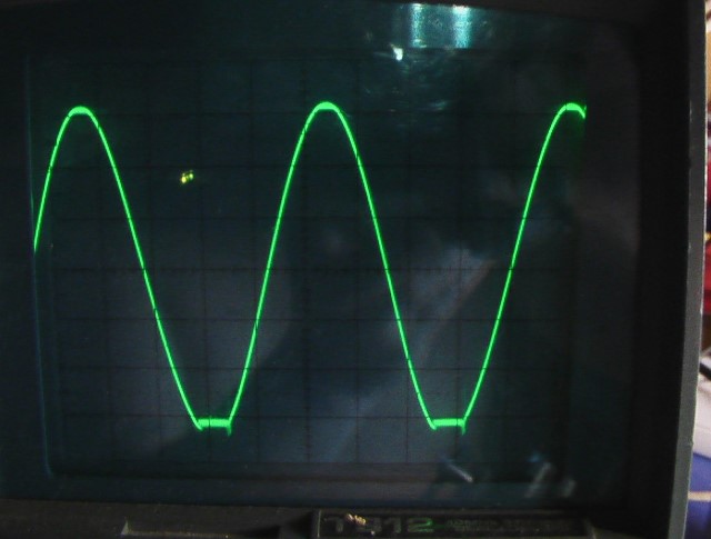
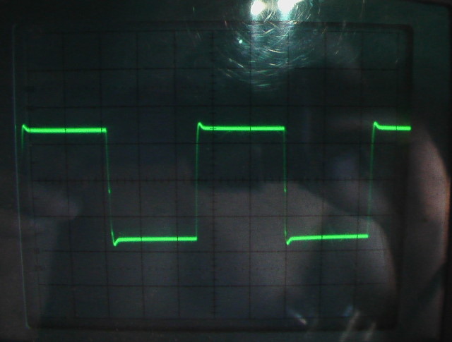
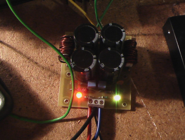
NMOS200 Scope pictures
My NMOS200 with R21 exchanged with Yellow LED (1.9V)
Much better clipping. Near symetrical
Same module and the 10khz Squarewave. Also less overshoot. Original signal from functiongenerator not shown here but was almost perfect (slightly undercompensated)
Nearly no sign of crossover.
My NMOS200 with R21 exchanged with Yellow LED (1.9V)
Much better clipping. Near symetrical
Same module and the 10khz Squarewave. Also less overshoot. Original signal from functiongenerator not shown here but was almost perfect (slightly undercompensated)
Nearly no sign of crossover.
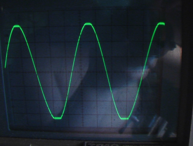
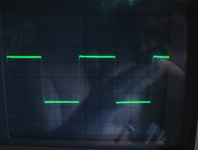
NMOS200 D.U.T.
Some testpictures from the above session.
The PSU is from Nordic's (on this forum) PCB layout. He is helping Carlos with the on going DX amp projects, as you may all have watched growing.
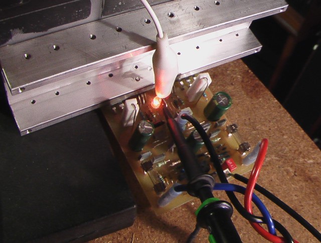
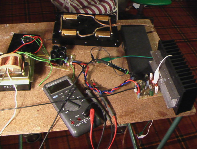
I'll come back tomorrow with distortion numbers. This forum is lagging severly this evening
Some testpictures from the above session.
The PSU is from Nordic's (on this forum) PCB layout. He is helping Carlos with the on going DX amp projects, as you may all have watched growing.
I'll come back tomorrow with distortion numbers. This forum is lagging severly this evening
Radioman62, is it yellow or amber (orange) LED? I tried orange, it didn't work.
This morning I tried only two diodes in the string instead of three. The voltage drop is close to 1.5 volts. Bias setting is not so sensitive but the distortion sets in too early.
I also tried a four diode string. But the results are again not very good.
In any of the configurations, the minimum bias I am able to get is between 60 and 70mA. Ofcourse, distortion is worse compared to Iq of say 170mA.
It appears that supply voltage of less than +- 45 volts is just not suitable for the NMOS amp, unless some other component values are changed significantly.
- Home
- Amplifiers
- Solid State
- Power amp under development