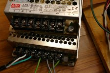
The Meanwell RS series and LRS series have voltage adjustment pots. Some of the cheaper clones do not. The pot is good for about 10% adjustment range, so it is possible that some 24 volt supplies will not go to 26 volts but both of mine do. Both of my 5 volts supplies will not go to 6 volts and neither 12 volt will go 15 volts, but I wouldn't expect them to. I don't think I have ever turned the screw on the 36 volt supply because I use it for 36 volt tubes.
A tube heater will draw as much as 10 X it's rated current at cold start. Some switchers will not start up into this load unless they are rated for considerably more than the tube heaters draw.
A tube heater will draw as much as 10 X it's rated current at cold start. Some switchers will not start up into this load unless they are rated for considerably more than the tube heaters draw.
Attachments
About to order passive components along with the iron for my DCPP build! 
Though I eventually would like to use bigger output tubes I think I will start with the stock 6JN6 tubes to follow Pete's intended original design.
I was going to use this PT
https://edcorusa.com/products/xpwr0...00ma-dual-6-3v-6a?_pos=1&_sid=d5e44af28&_ss=r
700V secondary, ~500V B+
and this OT
https://edcorusa.com/products/cxpp6...utput-transformer?_pos=5&_sid=f8603b1d2&_ss=r
6.6K primary impedance
Looking at the 6JN6 datasheet I don't see any issues running them at 500V at 6.6K.
Thoughts?
I love those things! I used two 5V units to power a 327-A filament (10.5V, 10.7A). I just stacked the outputs and set one to 5.5V. Meanwell made powering that monster oddball filament easy.The Meanwell RS series and LRS series have voltage adjustment pots.
The 7.5V units are great for old directly-heated types and 6.3V tubes (but you have to use a dropping resistor for 6.3V types since the supply won't quite adjust down to 6.3V).
I don't bother making filament/heater supplies anymore. I just buy them from Meanwell.
I wondered why you plan to get bigger iron than specified. More power? Why not then build the 50 watt mono amps?About to order passive components along with the iron for my DCPP build!
Though I eventually would like to use bigger output tubes I think I will start with the stock 6JN6 tubes to follow Pete's intended original design.
I was going to use this PT
https://edcorusa.com/products/xpwr0...00ma-dual-6-3v-6a?_pos=1&_sid=d5e44af28&_ss=r
700V secondary, ~500V B+
and this OT
https://edcorusa.com/products/cxpp6...utput-transformer?_pos=5&_sid=f8603b1d2&_ss=r
6.6K primary impedance
Looking at the 6JN6 datasheet I don't see any issues running them at 500V at 6.6K.
Thoughts?
I'm more of a Mouser guy myself so I am going to use these ones.What are you gonna use for caps that are on the board? I don't see anything over 500v @digikey.
jeff
25mm, will be a bit tight on the PCB but I'll make it work
https://www.mouser.ca/ProductDetail/EPCOS-TDK/B43541B8476M000?qs=GG15fDrrStppcmQTIURitg==
Yes more power.I wondered why you plan to get bigger iron than specified. More power? Why not then build the 50 watt mono amps?
I want to build a stereo amp rather than two monoblocks. After reading this thread it seems many people have "modded up" the original DCPP PCB to get more power this way.
Just looking for one last confirmation before pulling the trigger on the iron $$$!
BumpAbout to order passive components along with the iron for my DCPP build!
Though I eventually would like to use bigger output tubes I think I will start with the stock 6JN6 tubes to follow Pete's intended original design.
I was going to use this PT
https://edcorusa.com/products/xpwr0...00ma-dual-6-3v-6a?_pos=1&_sid=d5e44af28&_ss=r
700V secondary, ~500V B+
and this OT
https://edcorusa.com/products/cxpp6...utput-transformer?_pos=5&_sid=f8603b1d2&_ss=r
6.6K primary impedance
Looking at the 6JN6 datasheet I don't see any issues running them at 500V at 6.6K.
Thoughts?
Any of the "18 watt" sweep tubes works well under those conditions. They will start to run into dissipation issues if the B+ voltage gets much higher than 450 volts. This happens at idle, not max power as most builders assume. A typical push pull vacuum tube amplifier will see excessive crossover distortion at low volume levels unless the idle current is increased to allow class A or near class A operation in the first few watts of operation where the amp will spend most of its time unless it's used for blasting boom-boom music across the dance floor. As the idle current is increased from zero the THD at 1 watt of power output will improve from "ugly" to "acceptable" pretty quickly, then gradually improve after that.Personally, I'd stick with George's formula for the stock tubes. 6.6k primaries @450v B+ for 50 watts with pretty low distortion (see his post #139).
jeff
Most sweep tubes need 25 to 35 mA to get out of "acceptable" and into "can't hear it" range. 35 mA on 450 volts burns 15.75 watts in an 18 watt tube. That's OK in a TV sweep tube. 35 mA on 500 volts burns 17.5 watts. Maybe OK on well constructed tubes, but voltages higher than 500 volts will need bigger tubes even at low power levels. Remember that your B+ voltage will be higher at idle than at full power output. As stated 450 volts and a 6600 ohm OPT gets you to about 50 WPC.
Getting more power from 18 watt tubes is best done at lower B+ voltages and a lower impedance OPT. Here the idle current can be cranked up to clear the crossover distortion and the lower impedance OPT will extract more power from the tubes at a given voltage. The limiting factor for doing this in any push pull amp is the peak cathode current capability in the output tubes. This is where sweep tubes shine. A typical 6L6GC is limited to about 175 mA. The 18 watt sweep tubes used in this amp are rated for 550 mA. The 24 watt 6HJ5 and 6HD5 I used is good for 1 amp. More than 50 WPC is best done on about 450 volts and a 5000 ohm OPT, or even an OPT in the 4000 to 4500 ohm range. A 3300 ohm OPT on 500 volts pulls too much current through the output tubes if the amp will see high power output for extended periods of time.
My 125 WPC version of this board ran 6HJ5's on about 620 volts at idle which dropped to about 600 volts at full power. The OPT was 3300 ohms. I ran the idle current in the 30 to 35 mA range which burned about 20 watts per tube. One of my test amps at this power level did see some use as the PA amp for rock band during a couple of outdoor shows without issue, but I wouldn't trust the PCB layout on this design under those conditions for long term use. Peak plate voltages go over 2KV quite often when the amp sees clipping.
Thanks Jeff and George, this was the input I was hoping for!
The PT I am looking at has a 700V secondary (350-0-350) which should give me a B+ of 490V unloaded. I figure with tubes in the B+ should be ~450V.
450V B+ and 6K6 60W OT
Going to order the iron
I still don't quite understand how you can get 50W from a pair of 6JN6 which have a plate dissapation of 17.5W but I will have to let that thought simmer and think it over some more
A well designed class AB tube amp will usually have a plate efficiency in the 60% range. This means that the power supply puts 83.3 watts of power into the pair of output tubes, and 50 watts of audio output power comes out. This leaves 33.33 watts of power dissipated between two tubes for 16.66 watts per tube. We are not even breaking the rules yet. Even if the efficiency is about 50% there is about 25 watts burned up in each tube, which is over the spec limit but probably will not cause damage unless the amp is run at full power continuously.I still don't quite understand how you can get 50W from a pair of 6JN6 which have a plate dissapation of 17.5W but I will have to let that thought simmer and think it over some more
Look at it the same way Bob Carver did when he made all of those solid state amps with no heat sinks. If you put a sine wave into that amp and cranked it up to full power and left it there for some time, something would melt or otherwise fail. We don't normally listen to full power sine waves, we listen to music. Most music has at least a 20 dB peak to average ratio. Well recorded music is often better than that, and some uber compressed dance music may only have a 10 dB peak to average ratio, so let's use that 10 dB number.
This means that if you feed your 50 watt amp with some kind of boom - boom music and turn it up to the point where it is clipping on the peaks, the average power output is 5 watts. This does not raise the average dissipation much beyond the idle conditions. I used to play my 125 WPC version of this big red board at the clipping level, open the house windows, then go outside to mow my lawn without hearing the mower. It never blew up.
A pure class A amp dissipates the most power at idle since all of the power supply's energy is turned to heat. A pure class B amp will usually dissipate the most heat at full power output before clipping. A class AB amp will dissipate the most power somewhere between these extreme's depending on how hot the idle bias point is.
" A pure class A amp dissipates the most power at idle since all of the power supply's energy is turned to heat. A pure class B amp will usually dissipate the most heat at full power output before clipping. A class AB amp will dissipate the most power somewhere between these extreme's depending on how hot the idle bias point is. "
The point as I gather.. Everything is a trade off- these cases-
Pure class A-
Pro- Minimize distortion at low vol levels, perhaps also @ higher vol levels resulting in clean sound thru the range
Con- Less efficient.. Required higher idle current eats tubes, generates more B+ heat
Class AB-
Pro- More efficient (50-60%) less B+ current required. Less idle current, easier on output tubes
Con- More crossover distortion low watts, clears up higher vol levels
If error, please point. This post purpose to quantify basic up/downs
Jim
ps. seems a fixed bias source could be variably controlled by outside means to render best of both worlds
Last edited:
Sorry I forgot you mentioned the 800V is a work around
Mouser does have
https://www.mouser.ca/ProductDetail/STMicroelectronics/STP8NK80ZFP?qs=uepKQD%2BspxDUMJnl87v/dg==
The IXCP10M45 seems harder to find
Mouser does have
https://www.mouser.ca/ProductDetail/STMicroelectronics/STP8NK80ZFP?qs=uepKQD%2BspxDUMJnl87v/dg==
The IXCP10M45 seems harder to find
Digikey shows 400+ currently in inventory.
https://www.digikey.com/en/products/detail/ixys/IXCP10M45S/416792
https://www.digikey.com/en/products/detail/ixys/IXCP10M45S/416792

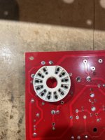
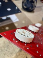
How hard should it be to fit the 12 pin tube sockets in to the PCB?
The pins are very tight in the PCB. I am not sure if I should force the sockets in more so they fit flush (parallel) to the PCB.
As they are fitted now the pins barely poke through the otherwise of the PCB.
The pins are very tight in the PCB. I am not sure if I should force the sockets in more so they fit flush (parallel) to the PCB.
As they are fitted now the pins barely poke through the otherwise of the PCB.
Attachments
- Home
- Amplifiers
- Tubes / Valves
- Posted new P-P power amp design