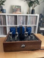
Up and running!
Still burning in and stabilizing but so far so good! The amp sounds great. I have the plates of the 6JN6 at 416V with the bias at 35mA (still trying to stabilize and balance the output tubes fully).
The cheap voltmeter on the front doesn’t work as intended. It’s so low impedance that even when it is put in parallel with thr 1R cathode resistors it throws off the measurements and doesn’t actuate reflect the bias current/voltage. Oh well, it looks cool, backlit by a super bright white led running off the filament supply.
EDIT: I forgot there is a bit of popping upon startup. Haven't had this before in a power amp. What is the best way to implement a mute function circuit?
In the past with preamps I have just shorted the output to ground but with a power amp I am not sure if I want to short the OT secondaries!
Attachments

If this is the cause of the instability, then disconnect it.The cheap voltmeter on the front doesn’t work as intended. It’s so low impedance that even when it is put in parallel with thr 1R cathode resistors it throws off the measurements and doesn’t actuate reflect the bias current/voltage.
Nice work, your amp looks sharp.

jeff
Good eye!
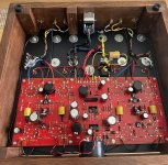
That little setup is actually for the bias supply. I am using larger iron on this build. The PT has a 130V-0V winding (no CT). As such, the 130V goes to a bridge rectifier, 16uF of filtering, then into a 3K 25W resistor to drop the voltage to -60V before going in to the PCB.
A question for you all:
My OTs are 6.6K whereas Pete's original design used 8K. I am wondering if I need to adjust the NFB resistor network at all?
I know if I moved from the 8R to 16R on the secondary side I would need to adjust the NFB, I am not sure about the primary though.
I ordered a few parts to start this several years ago, and recently decided to get back at it.
There’s 2 problems I’m having ordering the parts. The 600V mosfets are NLA, as are the 800V ones folks have suggested. Will the 900V (FQPF8N90C) ones still work? Mouser only had 12 left, so I ordered these
The carbon comp resistors. Can they be replaced with carbon film or something else? Can’t seem to get those either. I did order 1/4W 680 carbon comp resistors.
1/4 W nowadays are tiny. Depending on their function and dissipation in this circuit, they might smoke. Verify they are at least the same rated power as Pete mentionned in its BOM.
As for the FET I have used the 900V as well.
R69 (1M) must be 3W, on my amp the small ones kept blowing up.
As for the FET I have used the 900V as well.
R69 (1M) must be 3W, on my amp the small ones kept blowing up.
Yeah. That’s a good point. I am building this with the “boosted” B+ twin supply and 3300 ohm OPTs1/4 W nowadays are tiny. Depending on their function and dissipation in this circuit, they might smoke.
R69 (1M) must be 3W, on my amp the small ones kept blowing up.
Depends on what they are doing: C-comp for RF applications, such as stopper resistors. Otherwise, C-film or metal should be OK and have better noise performance. There are a couple of caviates: the film resistors don't stand up to momentary overloads as well as C-comp. The other thing to watch out for is the size. These days some metal oxide 1.0W resistors are the same size as 1/4W C-comps. It doesn't make a lot of difference in solid state work (low voltages) bit can be a problem with hollow state and the much higher voltages used there. To avoid flash-over when using these smaller types put three in series to reduce the voltage across each resistor.The carbon comp resistors. Can they be replaced with carbon film or something else? Can’t seem to get those either. I did order 1/4W 680 carbon comp resistors.
The grids are pulled low with R68, R70 3.3k resistors. You can leave out the wire from the OPT, or resistors 71 and 72
Tying the eye to ground won’t make a difference, it’ll just mean you can hook up the negative feedback later if you want.
Tying the eye to ground won’t make a difference, it’ll just mean you can hook up the negative feedback later if you want.
Last edited:
I am designing a chassic to be made by SendCutSend or other competitive sheet metal service for my DCPP. If there is other interest in a possible group buy I will start another thread so the group can collaborate on final features. The goal to have a chassis which looks great and requires a minimum of other fabrication skills. Below is the general concept 1. The top panel just matches the stock Pete layout, using mounting holes for the stock Edcor transformer set. The front panel has cutout for the cheap Chinese SO-45 round panel meters for tube bias readings. Not yet shown are access holes from accessing the adjustment pots from the top. The rear has cutouts for the stock AC module, Neutric RCA jacks and Pomona binding posts. It will require end pieces routed (preferably) out of the wood or other material of your choice. Questions, comments and criticisms are welcome.

Actually I can get a router template laser cut also as part of the package out of aluminum. It would add negligible cost to the order.Will look really nice with some wood sides, and should be relatively easy to make a router template to cut a matching groove in them.
I have modified the concept a bit. I extended the front flange to make room for a 2gang stepped potentiometer and hole feature for it in the flange. I drive my amps directly from line level. I know this may not be everyone's cup of tea, and if others may want this without the hole for it, that can be done. (But that raises the lot cost). Or the I can have tiny pilot holes cut and people can drill out there own holes. Also added are the pot adjustment access holes.
I will add a model of the bottom ventilated plate as tonyp063 suggested. But not sure if I will have that laser cut or first see if there is precut perforated aluminum sheet available for cost optimization.
Also thinking of anodizing and color. I am not very artistic of picking colors. This simple concept is blue to match the Edcor blue. Maybe basic black is the way to go.
Final rendition for this thread. To make the rendering complete I modeled the tubes and heatsink. I found these CUI heatsinks work well enough on keeping the mosfets cool at the stock operating points. Plus I think they give a nice visual balance in the center of the large top-plate. Cost estimates. For a one-off, most expensive option, the sheet, cutting and bendng comes to about $125 each. If ordered 10 at time it drops to ~$55 each. That does not include anodizing or other finishing. I can anodize these at my home setup (I think) or these can be powder coated moderately economically locally.
If there is interest I will start another thread to coordinate the buy. I am probably a least month away before I order one for my self, I have a little more benchwork on my board before I seal it up.

If there is interest I will start another thread to coordinate the buy. I am probably a least month away before I order one for my self, I have a little more benchwork on my board before I seal it up.
- Home
- Amplifiers
- Tubes / Valves
- Posted new P-P power amp design