Thats good... did you use Diptrace to do the PCB by any chance ?
Very neat")
Thanks
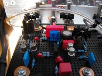
The layout is done in Eagle, DRC was set on min 10mil between tracks.
I misread my drillbits and drilled most of the holes with a .9mm drill when I thought I was using a .6mm one...
I tried getting the board under 5x5cm(seeedstudio, 9.90$ for 10 pieces) but there was no way that was happening. Not that I would order it anyway, I just enjoy the challenge. Finished design will be a bit bigger, with mounting holes and horizontal resistors.
-
Kolbjørn
New Gold Member
Hi,
Last year i finished my new amp.
It is a shiny 2x18 watt retro influenced solid state amp.
Every transistor is from the late 60's but the circuit is more like the blameless amp from Douglas Self.
It has a build in RIAA correction amplifier for Vinyl playback and 2 additional inputs for CD or Ipod etc.
The whole thing is designed and simulated in Multisim 2001 and build on experimental (vero board) print that has been painted Black.
Works like a charm and sounds super smooth, I really like it.
And the modest 2x18 watt is more than enough for me.
Hope you guys like it.
Attachments
No picture, but bought an Onkyo push pull with WRAT technology, model # TX -NR3008, hasn't been shipped yet and last one available unopened box. I also bought a 15 amp powercenter and I need to replace wiring and put a 20 amp fuse for high amp digital circuitry protection and a 20 amp fuse for high amp analog. I lost old username, etc. I've been sick for 4 years and my computer was destroyed by people I thought were friends, or else I'd be still posting with old username, etc. Please, I blew my B&K AVR507 updated to V3 and everything is explained under solid-state, but haven't been able to have post's posted, because a moderator needs to see if I'm a home theater nerd, or a for real DIY audiophile junkie, which my old posts would prove, so I understand and need to go to doctor's appt, so I'm posting and reposting as to let mod see I'm for real, but need to go. Thanks for your time.
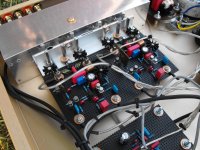
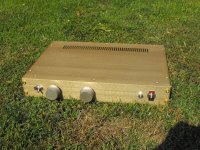
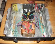
This is my second Leach amp -just finished.
Sounds good. Some of internal wires has not yet been arranged and enclosure cleaning still needed.
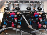
DC offset - 16mV and 3mV. 20Khz square wave you can see in photo.
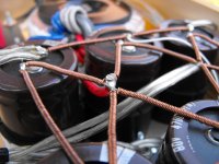
Transformer 350VA. 6x4700uf per rail. No hum - measured about 0.05-0.08mV without shorted inputs.
Transistors from original article. bias- 100mA.


Sounds good. Some of internal wires has not yet been arranged and enclosure cleaning still needed.
DC offset - 16mV and 3mV. 20Khz square wave you can see in photo.
Transformer 350VA. 6x4700uf per rail. No hum - measured about 0.05-0.08mV without shorted inputs.
Transistors from original article. bias- 100mA.
Awesome leach build , MUCH better than most. Triple OP is the only way to go, took me over 2 years to realize this.
OS
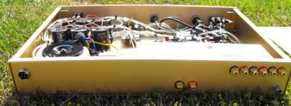
This is my second Leach amp -just finished.
Sounds good. Some of internal wires has not yet been arranged and enclosure cleaning still needed.
Chassis from Russian amp 
Regards zeoN_Rider
Banned
Joined 2002
hot or not
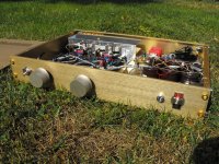
what size your heatsinks are your amps mosfet or bipolar ?Here's another shot. You can see the speakers to the rear and the source (cd player) to the right.
Tnx guys!
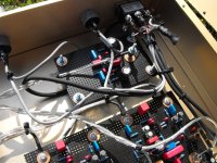
zeoN_Rider : Only radiators comes from the old dead Russian amp. Aluminum panels are cut from 3mm thick sheets and then punched.
ostripper: I also like the triple output, one day i will try some of your modern
design too !
I intend to put the leach amp to "bed"
(I still like it - a real classic). The spirit of DIY is NOT buying the prebuilt cases and spending the $$$ , but to clean the earth of all that E-waste and make the best amps we can. Classic pro-amp enclosures , with some tender care .... can have a NEW LIFE (BELOW ! - $40usd , with the caps ) .Next pictures I post will be of the completed ... "21st century triple"
(below 2 - that is what a triple can really do , low loop gain- 65db !)
OS
Attachments
The DB Amp
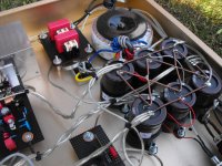
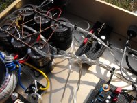
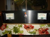
This amp was built from L20 circuit boards, power supply boards, soft start module board and speaker protection relay board all obtained on Ebay. The transformers are from Plitron surplus stock. They are rated at 40-0-40 volts @2.75 amps. The VU meters and driver boards were obtained from a company in Australia (JLM audio), they measure the amps output at the speaker terminals.
I had the not so bright idea of cooling with Peltier devices and being able to use smaller heat sinks. The Peltier devices did not pan out and I was left with the small heat sinks. So a thermal switch has been installed that will cut the AC if the temperature reaches 85 degrees C. so far, the heat sinks get quite warm but not too hot to touch. However, I have yet to leave it on for more than 2 hours.
The amp was built to replace an aging Yamaha M-70 amp which was being repaired far too often. My calculations said it would be cheaper to build than keep on repairing a 25 year old amp. The sound compares favourably with the Yamaha M-70. The DB seems slightly less grainy and more detailed than the Yamaha.
When it comes to building I am definitely not the artisan that you quite often find gracing the forums at DIYAUDIO. DB stands for "dog's breakfast" in honor of my chaotic wiring.
Attachments
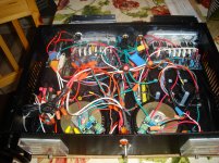
This amp was built from L20 circuit boards
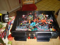
Wiring is like spaghetti
Regards zeoN_Rider
Sometimes spaghetti wiring is actually a good thing. But you don't see that many house-wiring wire nuts in many amps.
There is nothing like a wiring loom to cross induce signals.
There is nothing like a wiring loom to cross induce signals...... Sometimes spaghetti wiring is actually a good thing..........
Wiring is like spaghetti
not necessarily.Does neat wiring make it sound better
Correct wiring will sound better than incorrect wiring.
My most important finding over the decades has become:- that current flows around a circuit. That circuit must have a Flow and Return route. That Flow and Return route must have minimum loop area. Except when the circuit is part of a transmitting or receiving aerial.
Last edited:
- Home
- Amplifiers
- Solid State
- Post your Solid State pics here