dear farjon,...this is my Baby Aksa's version.
See here and subsequent posts:
http://www.diyaudio.com/forums/solid-state/168554-based-hugh-deans-aksa-55-a-62.html#post2780494
The thread:
http://www.diyaudio.com/forums/solid-state/168554-based-hugh-deans-aksa-55-a.html
In time... I was previously the "Sound_Buster". Now I'm using "Farjon", unifying my nickname around many Forums.
.
.
can u share both amplifier and protection pcb,s. thanking you masood
I suggest a new thread be opened: "unsafe practices". everytime a user posts a pic and is deemed to be an unsafe practice just quote the pic, a symbol for danger and a link to the new thread where that pic will be systematically checked and commented. nothing more. Please mods consider this proposal.
AndrewT a word of advice from someone himself prone to harsh comments: keep your tone in place. It was not long ago you ventured in a 6 post rant about a sentenced I never wrote.
")
Inviato dal mio GT-I9001 con Tapatalk 2
AndrewT a word of advice from someone himself prone to harsh comments: keep your tone in place. It was not long ago you ventured in a 6 post rant about a sentenced I never wrote.
Inviato dal mio GT-I9001 con Tapatalk 2
you have so many people applying bad practice and bad techniques both regarding safety and sound
Normally the forum people that post this type of negative criticism is the people that have learned from their mistakes the hard way ...that will include plenty of BJT ( grey smoke ) mosfets ( blue smoke ) and woofers blown to the moon ..
So yes this criticism might sound negative but comes from real experience....
 I think it is was in general to keep try and keep to pictures with a little discussion of what is posted.
 mod hat off. I think it is important that if someone sees something unsafe in a picture that is posted that they say something. However it should be said in a constructive way, be gentle and point out the problem. Don't do it in a way that is just going to get the persons back up.
example 1 (bad) "your an idiot and are likely to kill yourself or someone else, give up electronics as a hobby before you kill someone!"
example 2 (better) "I'm very concerned about X, It is potentially lethal for reasons X Y Z. Please fix it or you or someone you love could end up dead".
The first is just going to get the persons back up and they won't necessarily listen or fix it (and it should earn you an infraction as well). The second hopefully would still get the message across without getting the person off side.
Tony.
Pictures yes, but discussion is useful
While the pictures are the best part of this forum, I find the discussion the more valuable in terms of advancing my meager diyaudio skills. Some of the rants about safety I have found to be silly. An example being the "soft start" circuit always on AC when an external switch negates this problem which none of the ranters mentioned. They actually would not allow the circuit diagram on the forum! I think the tone of criticism could be tempered in many cases. Suggestions rather than imperatives should be the case. But keep the discussions. AndrewT' s tone in my opinion has been a tad harsh but at the same time I am grateful he contributes to this forum because he has advanced my knowledge. I hope AndrewT and the rest of the forum will continue to offer advice and opinions on the pictures submitted. Please be gentle.
While the pictures are the best part of this forum, I find the discussion the more valuable in terms of advancing my meager diyaudio skills. Some of the rants about safety I have found to be silly. An example being the "soft start" circuit always on AC when an external switch negates this problem which none of the ranters mentioned. They actually would not allow the circuit diagram on the forum! I think the tone of criticism could be tempered in many cases. Suggestions rather than imperatives should be the case. But keep the discussions. AndrewT' s tone in my opinion has been a tad harsh but at the same time I am grateful he contributes to this forum because he has advanced my knowledge. I hope AndrewT and the rest of the forum will continue to offer advice and opinions on the pictures submitted. Please be gentle.
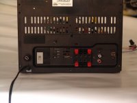
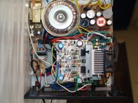
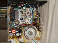
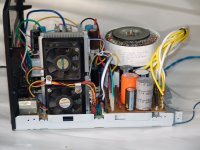
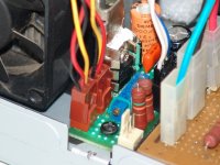
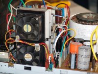
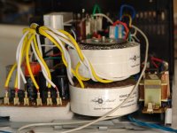
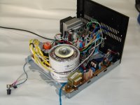
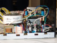
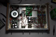
An amp built from junk parts deserves a recycled case!
A friend of mine asked me to fix his stereo, and I decided to place a new stuff inside the case!
Circuit from http://www.diyaudio.com/forums/soli...d-amplifier-out-junk-parts-4.html#post2180731
Sorry, I forgot to take a picture after finishing the job!
Regards,
Max.
A friend of mine asked me to fix his stereo, and I decided to place a new stuff inside the case!
Circuit from http://www.diyaudio.com/forums/soli...d-amplifier-out-junk-parts-4.html#post2180731
Sorry, I forgot to take a picture after finishing the job!
Regards,
Max.
Attachments
-
 DSC05381.JPG129.2 KB · Views: 1,289
 -
 DSC05409.JPG185.4 KB · Views: 520
 -
 DSC05403.JPG190.1 KB · Views: 430
 -
 DSC05396.JPG159 KB · Views: 380
 -
 DSC05393.JPG171.1 KB · Views: 436
 -
 DSC05391.JPG202.7 KB · Views: 1,147
 -
 DSC05389.JPG148.9 KB · Views: 1,194
 -
 DSC05388.JPG145.9 KB · Views: 1,238
 -
 DSC05387.JPG170.3 KB · Views: 1,258
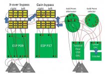
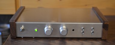
My preamplifier!
I've been working on this on & off since last fall, and it's still not finished!
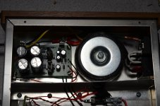
Power supply
· Schurter Power Entry Module. Mains input, dual fuses and power switch all in one convenient package!
· Triad Magnetics 25VA 30V torroidal transformer
· Another power switch, this one on the front of the chassis.
· Elliott Sound Products P05, Preamp Power Supply Regulated for 30VDC with a 30VAC input.
Inputs
· Twisted Pear USB receiver module
· SpeakerNet TOSLINK optical input module. This will probably operate off a 9V battery when it gets installed.
· ES9023 / WM8804 S/PDIF DAC. This is an active group buy on diyAudio being run by Unixdeveloper. I’m still waiting for a BOM and boards. It will have an on-board power supply, but I don’t know how I’ll power it yet. Space is available in the chassis next to the Twisted Pear DAC, above the barrier strip & fuses. The hole on the front of the chassis is for its on/off switch.
· One pair of good old-fashioned analog inputs. I don’t have room on the back of the chassis for any more RCA jacks.
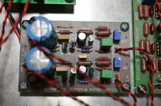
Gain Module
· Elliott Sound Products P37 Minimalist HiFi preamplifier.
· Bypass switches are the best I could find: NKK Switches M series.
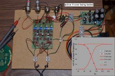
Active X-over
· Elliott Sound Products P09 Linkwitz-Riley crossover built for 80Hz knees. This has a long, sad, story. I built this using all polypropylene caps and Burr Brown OPA2134 opamps, including the optional buffers. The big polypropylene caps wouldn’t fit on the board, so I did things like soldering components to the bottom of the board, and combining series resistors with one 2X resistor to save space. I couldn’t get it to work using my oscilloscope to measure output. I tested and tested and replaced a bunch of components, and posted questions on the ESP forums, but no joy. I got nothing but very low voltage noise at the outputs. I gave up, bought a new board and built the second one exactly as Rod instructed. I used ceramic caps which fit on the board, Texas Instruments TL072 opamps (not as nice as the Burr Browns) and skipped the buffers for simplicity. Again – nothing. Out of ideas, and desperate, I hooked up a CD-player to the inputs, and a receiver & speakers I was willing to sacrifice to the outputs and . . . music! It turned out the outputs need some conductance between positive & ground for the module to work. My oscilloscope does not provide any conductance between the leads. I put 50K resistors across all outputs and ground and tested again with my scope, and it behaved beautifully. Because I took some parts from the first built for the second build, I decided to put the second build (with cheaper opamps and ceramic caps) into the preamplifier. In hindsight I wish I had gotten the first build working (again?) and used it, maybe without the unnecessary buffers.
· Bypass switches, also NKK Switches.
What’s up with all those switches?
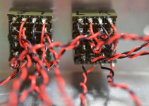
· I decided to keep all signal wires tightly twisted with their respective ground wires as much as was possible. The theory (untested) is that this will minimize RFI coming from all those D/A converters, and also prevent unwanted voltages differences from arising as the signal wires went all over the chassis. This means that the gain module and the active X-over bypass switches needed to be 2-pole, 8-throw each!
I divided them up into two 4-pole switches, one for before, and one for after, the module/bypass. I’m actually bypassing 2 modules – gain stage and active X-over - so that’s four 4-pole switches. You can’t imagine what it was like to do all that soldering. Or maybe some of you can.
Miscellaneous
· Chassis by Hammond Manufacturing # 1444-22CWW.
· Signal wiring by Apex Jr. PTFE Silver Plated Stranded Copper Wire, 24 AWG I think.
· Power wire courtesy of Radio Shack, 18 AWG, single stranded.
· RCA phono jacks by Amphenol Audio. These are the best RCA jacks ever, and ground is shielded from the chassis.
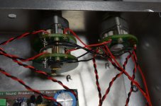
· Gold Point Mini-V, 2 channel, 50K (input resistance of my amp) stepped attenuator
· Gold Point 6 pole 2 throw (2 channel) selector
I'm really tired of working on this,and I'm glad I'm finally finished.
I've been working on this on & off since last fall, and it's still not finished!
Power supply
· Schurter Power Entry Module. Mains input, dual fuses and power switch all in one convenient package!
· Triad Magnetics 25VA 30V torroidal transformer
· Another power switch, this one on the front of the chassis.
· Elliott Sound Products P05, Preamp Power Supply Regulated for 30VDC with a 30VAC input.
Inputs
· Twisted Pear USB receiver module
· SpeakerNet TOSLINK optical input module. This will probably operate off a 9V battery when it gets installed.
· ES9023 / WM8804 S/PDIF DAC. This is an active group buy on diyAudio being run by Unixdeveloper. I’m still waiting for a BOM and boards. It will have an on-board power supply, but I don’t know how I’ll power it yet. Space is available in the chassis next to the Twisted Pear DAC, above the barrier strip & fuses. The hole on the front of the chassis is for its on/off switch.
· One pair of good old-fashioned analog inputs. I don’t have room on the back of the chassis for any more RCA jacks.
Gain Module
· Elliott Sound Products P37 Minimalist HiFi preamplifier.
· Bypass switches are the best I could find: NKK Switches M series.
Active X-over
· Elliott Sound Products P09 Linkwitz-Riley crossover built for 80Hz knees. This has a long, sad, story. I built this using all polypropylene caps and Burr Brown OPA2134 opamps, including the optional buffers. The big polypropylene caps wouldn’t fit on the board, so I did things like soldering components to the bottom of the board, and combining series resistors with one 2X resistor to save space. I couldn’t get it to work using my oscilloscope to measure output. I tested and tested and replaced a bunch of components, and posted questions on the ESP forums, but no joy. I got nothing but very low voltage noise at the outputs. I gave up, bought a new board and built the second one exactly as Rod instructed. I used ceramic caps which fit on the board, Texas Instruments TL072 opamps (not as nice as the Burr Browns) and skipped the buffers for simplicity. Again – nothing. Out of ideas, and desperate, I hooked up a CD-player to the inputs, and a receiver & speakers I was willing to sacrifice to the outputs and . . . music! It turned out the outputs need some conductance between positive & ground for the module to work. My oscilloscope does not provide any conductance between the leads. I put 50K resistors across all outputs and ground and tested again with my scope, and it behaved beautifully. Because I took some parts from the first built for the second build, I decided to put the second build (with cheaper opamps and ceramic caps) into the preamplifier. In hindsight I wish I had gotten the first build working (again?) and used it, maybe without the unnecessary buffers.
· Bypass switches, also NKK Switches.
What’s up with all those switches?
· I decided to keep all signal wires tightly twisted with their respective ground wires as much as was possible. The theory (untested) is that this will minimize RFI coming from all those D/A converters, and also prevent unwanted voltages differences from arising as the signal wires went all over the chassis. This means that the gain module and the active X-over bypass switches needed to be 2-pole, 8-throw each!
2 channels X signal & ground X before & after bypass: 2 X 2 X 2 = 8
Miscellaneous
· Chassis by Hammond Manufacturing # 1444-22CWW.
· Signal wiring by Apex Jr. PTFE Silver Plated Stranded Copper Wire, 24 AWG I think.
· Power wire courtesy of Radio Shack, 18 AWG, single stranded.
· RCA phono jacks by Amphenol Audio. These are the best RCA jacks ever, and ground is shielded from the chassis.
· Gold Point Mini-V, 2 channel, 50K (input resistance of my amp) stepped attenuator
· Gold Point 6 pole 2 throw (2 channel) selector
I'm really tired of working on this,and I'm glad I'm finally finished.
Attachments
-
 preamplifier from PowerPoint.jpg123 KB · Views: 638
 -
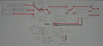 preamp wiring diagram.jpg197.7 KB · Views: 525
 -
 active X-over 2_testing_small.jpg305.5 KB · Views: 609
 -
 preamp finished insides_switches_small.jpg157.4 KB · Views: 597
 -
 preamp finished insides_Gold Point_small.jpg210.8 KB · Views: 1,374
 -
 preamp finished insides_gain module_small.jpg277.6 KB · Views: 1,468
 -
 preamp finished insides_PS_small.jpg255.1 KB · Views: 1,579
 -
 preamp finished insides_top view_small.jpg320.8 KB · Views: 1,666
 -
 preamp finished_front_small.jpg116.2 KB · Views: 1,668
A friend of mine asked me to fix his stereo, and I decided to place a new stuff inside the case!
Circuit from http://www.diyaudio.com/forums/soli...d-amplifier-out-junk-parts-4.html#post2180731
Sorry, I forgot to take a picture after finishing the job!
Regards,
Max.
Great job.....
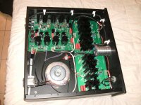
Quad update.
Hi,
had my Quad 33 24 hours now and thought it was time to bring the casework into the 21st century.
It won't be a quad inside just now and it matches my other gear, so I thought it worth doing.
Hi,
had my Quad 33 24 hours now and thought it was time to bring the casework into the 21st century.
It won't be a quad inside just now and it matches my other gear, so I thought it worth doing.
An externally hosted image should be here but it was not working when we last tested it.
I've been working on this on & off since last fall, and it's still not finished!
pretty neat job ... i like the case ...eventhough hand made its a good job ...
only i see as a negative is the wiring and bypass switching ... i presume that the switch was costy but also the wiring from and to the board will increase crosstalk figures by far ( especially with this type of wiring )
One could go with a couple of relays and minimize distance and crosstalk ...
Just an opinion .... still its a nice "handy" job !!!
Last edited by a moderator:
the wiring from and to the board will increase crosstalk figures by far ( especially with this type of wiring )
One could go with a couple of relays and minimize distance and crosstalk
Yes. I had to weigh the distortion of the gain module (when not needed) against the distortion of the extra wires and switches. And same with the active X-over. I guessed the crosstalk/distortion of the extra wires and switches would be less than that of the gain module, and the active X-over. Relays may give me the best of both worlds. I'll look into relays, as I know nothing about them. I can also probably shield the wires, and hold them away from the boards and from each other. I also may decide to always use the X-over, once I get the subwoofer amp and subwoofers built.
Thanks for the suggestions.
My apologies to the Moderators, this will be my last post in this thread without any picture attachments.
I regret that my previous post has generated some debate. Some seem to have latched on to the first part about criticisms that may not encourage members to post pictures. Do read that there is a second part that encourages those who are passionate and have the know-how to share their expertise by posting write-ups or technical how-tos.
I wholeheartedly agree with Richard Jenkins that a separate thread for sharing this sort of build knowledge and best practices is the best way to go. If you think about it, the current "predatory" (e.g. wait for a picture, then blast it) method of teaching leaves much to be desired. Also, what about all those newbies who did not post any pictures? They might have safety hazards that they are not yet aware. Don't you want to save them from a painful (and potentially lethal) experience? Why limit your teachings to just those members who view this thread?
At work, we have something called Technical Progression (duh) for engineers. As you get higher in rank, the main guiding principle for performance evaluation is not how well you know your stuff, but how well you enrich the engineering community. Naturally, the senior engineers that guide, mentor and teach are the ones who do well and the senior ones that yell, criticise and berate find themselves with nobody appreciating what they may have to offer.
Thank you for reading this post.
- Home
- Amplifiers
- Solid State
- Post your Solid State pics here