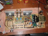
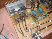
eventhough its a very neat and compact construction one thing i wouldn't do is to place electrolytics horizontally ....
Addition to that is that in the manuals of most capacitor manufacturers there is notes regarding horizontal installation and directions like when this is done the + lead should be on the upper side or so ( if someone may add some info on that would be very welcome or explain why )
kind regards
sakis
Last edited:
add some info
Depends where the safety valve is located.
For the types it applies to, mounted with negative terminal up, the pugh that fixates the winding lead to the terminal melts when the capacitor overheats, subsequently blocks the vent : Big-Bada-Boom (5th element)
(the Epcos lytic as used in the piccy has the pressure release valve situated on the center line)
I've heard of interconnect flame wars, but electrolytic gravity wars?! Don't mount the vent rammed up against an enclosure wall, or reverse polarise them, or strap them across the mains, but really?
Surely, a more important way to treat electrolytics is to ensure your well within the rated voltage?
Surely, a more important way to treat electrolytics is to ensure your well within the rated voltage?
You guys are not encouraging DIYers to post pictures.
"Wrong cable types"
"Wrong cable routing"
"Wrong cap orientation"
"Wrong led color"
"Wrong/Improper this/that"
Nobody wants to jump into a pool of sharks eager to tear their victims apart.
Now if you're really such pros, post a picture of how you'd do things better so the readers can learn. Alternatively, share your wisdom in the form of technical write-ups or how-to's.
Thread title doesn't say "Post your solid state pics here ... and get your work picked apart"
Now can we get back to pictures please?
Now if you're really such pros, post a picture of how you'd do things better so the readers can learn. Alternatively, share your wisdom in the form of technical write-ups or how-to's.
Now can we get back to pictures please?
Like this?

Attachments
Pictures stimulate discussion. And not always in a negative way. When you see something that's blatantly unsafe, or that's clearly against accepted standards and best practice, should't it be pointed out to the user? You don't need to dwell on it, but that's how people learn. Without saying anything it as much as tacit approval.You guys are not encouraging DIYers to post pictures.
"Wrong cable types"
"Wrong cable routing"
"Wrong cap orientation"
"Wrong led color"
"Wrong/Improper this/that"
Nobody wants to jump into a pool of sharks eager to tear their victims apart.
Now if you're really such pros, post a picture of how you'd do things better so the readers can learn. Alternatively, share your wisdom in the form of technical write-ups or how-to's.
Thread title doesn't say "Post your solid state pics here ... and get your work picked apart"
Now can we get back to pictures please?
That's why I don't necessarily post pictures of my projects until they starts to come together in the enclosure. A lot of latitude should be given anyone in the bread-boarding stage when it looks like a rats nest of wiring.
You are behaving like a fool...........Thread title doesn't say "Post your solid state pics here ... and get your work picked apart"
Now can we get back to pictures please?
This is for pics. This is where many will come to see and copy ideas/implementations.
This is where I will post if I see some thing that should not be copied.
You will not stop me posting here if I think it is necessary.
When you see something
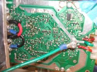
Might have been smarter to point Jacob at the way he mounted the block bridge rectifiers instead of arguing with others on a piccy thread.

I'm almost finished with my latest SS amp prototype #1. It is a stereo module. The idea is, all that is required to operate this module is to mount it into an enclosure, mount the bracket to a heatsink, connect 35VAC (5 to 7 Amps) to the wiring block. Connect the input and the speakers and that's it.
The circuit has a few features other than just the amplifier circuits. As you can see the PS is on the board. There are two rails, +/-24V (high current) and +/-48V (~12mA). +/-48V comes from a half wave voltage doubler and is then regulated to two seperate +/-40V sources to power the VAS for each channel. At this point not all the PS caps are in and not all the components are soldered, but both channels work now as does the logic. Notice there are no speaker relays. The output stage circuits are switched on and off by solid state and so there is no need for relays, eliminating the relay contacts in series with the speakers.
There is a LED and momentary switch that is attached with a wire strip and mounts to the front of the enclosure indicates status by showing blue for stand-by, green for active and will turn from green to red for ~0.3 Sec and then back to green if either channel is driven into clipping. Also there is a DC output detection circuit that if either channel output greater than +/-0.6V the logic switches the amp back into stand-by mode.
I will start a thread to discuss some of the circuits on this module, but I must plead non-disclosure to some of it, at least on this free public forum.
Attachments
Last edited:
Kudos CBS on tackling SMDs. I haven't gone there yet other then mounting a couple on brown dog adapters. What kind of output devices does it use? Was this a kit, and if so, can you provide a link to your source? Is it working yet? How does it sound?
You're 'almost finished'. Ok, I'll wait till your done.
You're 'almost finished'. Ok, I'll wait till your done.
Last edited:
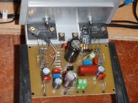
As someone asked...
...this is my Baby Aksa's version.
See here and subsequent posts:
http://www.diyaudio.com/forums/solid-state/168554-based-hugh-deans-aksa-55-a-62.html#post2780494
The thread:
http://www.diyaudio.com/forums/solid-state/168554-based-hugh-deans-aksa-55-a.html
In time... I was previously the "Sound_Buster". Now I'm using "Farjon", unifying my nickname around many Forums.
.
.
Attachments
- Home
- Amplifiers
- Solid State
- Post your Solid State pics here