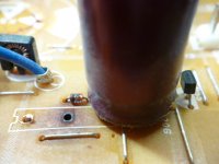
Here is the proof I'm so against PCB's.....this section of a power supply board, failed. The wirewound resistor despite being heat scorched still has the correct resistance; the fault occurred in the copper track which ran under it. After years of expansion/contraction from the heat, the track finally fractured.
Unsuprisingly, many computer aided pcb designs fall right into this trap.
richy
Why unsurprising? It is nothing to do with the fact that the design may or may not have been computer aided, or on a PCB. It is do do with the fact that the designer(s) did not place the parts correctly relative to one another, and quite probably under-rated the wire-wound resistor. That can happen just as much with a point-to-point design.
I have used PCBs and point-to-point (and have also laid out many analogue and digital PCBs profesionally - from 1 to 10 layers). The end result using either technique is always only as good as the care and understanding that goes into the process.
and quite probably under-rated the wire-wound resistor. That can happen just as much with a point-to-point design.
looks pretty under rated to me, it also looks like the resistor was placed on the underside of the pcb and the heat has risen up to scorch the board from underneath.
Conceivably the designer has decided that cost was a serious factor and used a lower value OR that having the resistor mounted to the chassis or ontop of the pcb was too much of a hassle.
So even if he did rate the component properly he would have still screwed up on the fact that the resistor was on the underside of a pcb board, very strange behaviour indeed.
But not strange when you consider that corporations are using the planned obsolescence guidebook and following it to the letter.
This my fellow gents is sabotage, pure and simple cold blooded sabotage.

Last edited:
If valves are mounted to a PCB,
I prefer to use surface mount sockets and support the PCB with stand offs that support the tube bases and hard wire to the board..
If you are a superfi guy/gal then the question is sometimes raised does the fiberglass dielectric effect sound acting as a cap between tracks..for a normal build this is less of a problem..(If it is a problem") ) Whats the point of silver lead out caps connected to a copper track on a PCB?
) Whats the point of silver lead out caps connected to a copper track on a PCB?
I still like PTP even on a plain PCB or using the copper to solder mount the tag strip. use the copper as a screen to keep heater wiring shielded.
Hot parts and valve bases create dry joints when one part of the connection is fixed and the other moves with expansion. Perhaps Ok with preamp tubes and hard wire power tubes.. I still think of a PCB a temporary (X years)compared to a PTP build. In industry PCB is the standard now however component change is always a problem with age lifting tracks. Then again if I was building SS then PCB is the way to go. Nothing wrong with PCB as a sort of discrete component in a PTP build.
You can also mount the copper covered PCB inside a wooden case and this gives the effect of a top plate that can be earthed and the tag strip soldered onto the copper no screws to worry about..
I never thought about microphonics compared to PTP and PCB..I did melt candle wax over a PCB for a laugh...its strange how you convince yourself that the treble sparkle had all gone..I wasn't happy untill I stripped the wax off the board..LOL..I tried it after using black tack under caps etc just for fun..
Regards
M. Gregg
I prefer to use surface mount sockets and support the PCB with stand offs that support the tube bases and hard wire to the board..
If you are a superfi guy/gal then the question is sometimes raised does the fiberglass dielectric effect sound acting as a cap between tracks..for a normal build this is less of a problem..(If it is a problem
) Whats the point of silver lead out caps connected to a copper track on a PCB?I still like PTP even on a plain PCB or using the copper to solder mount the tag strip. use the copper as a screen to keep heater wiring shielded.
Hot parts and valve bases create dry joints when one part of the connection is fixed and the other moves with expansion. Perhaps Ok with preamp tubes and hard wire power tubes.. I still think of a PCB a temporary (X years)compared to a PTP build. In industry PCB is the standard now however component change is always a problem with age lifting tracks. Then again if I was building SS then PCB is the way to go. Nothing wrong with PCB as a sort of discrete component in a PTP build.
You can also mount the copper covered PCB inside a wooden case and this gives the effect of a top plate that can be earthed and the tag strip soldered onto the copper no screws to worry about..
I never thought about microphonics compared to PTP and PCB..I did melt candle wax over a PCB for a laugh...its strange how you convince yourself that the treble sparkle had all gone..I wasn't happy untill I stripped the wax off the board..LOL..I tried it after using black tack under caps etc just for fun..
Regards
M. Gregg
Last edited:
looks pretty under rated to me, it also looks like the resistor was placed on the underside of the pcb and the heat has risen up to scorch the board from underneath.
Conceivably the designer has decided that cost was a serious factor and used a lower value OR that having the resistor mounted to the chassis or ontop of the pcb was too much of a hassle.
So even if he did rate the component properly he would have still screwed up on the fact that the resistor was on the underside of a pcb board, very strange behaviour indeed.
But not strange when you consider that corporations are using the planned obsolescence guidebook and following it to the letter.
This my fellow gents is sabotage, pure and simple cold blooded sabotage.
Look under a Jap/chinese TV from the 1980's....shock and awe...one isn't alone in modifications and it goes on all the time on the PCB under. I've seen this done on the best music consoles too !
Last edited:
Well he said the resistor still had the correct resistance surprisingly after that much scorching you would think it would of drifted somewhat but the factors of age and time plus that heat expanding/contracting just weakened the trace etc
No. If it's a wire-wound, then the resistance may change only a very little despite the part reaching very high temperatures. The simple fact is that it got hot enough to burn the board and to apparently melt the solder joints (judging by their appearance) and that's down to the component rating and its placement.
Of course, it could be that it only got that hot due to a fault condition elsewhere, but that could also potentially have been anticipated and dealt with in the design. Again, nothing to do with PCB vs point-to-point construction.
Here is the proof I'm so against PCB's.....this section of a power supply board, failed. The wirewound resistor despite being heat scorched still has the correct resistance; the fault occurred in the copper track which ran under it. After years of expansion/contraction from the heat, the track finally fractured.
Unsuprisingly, many computer aided pcb designs fall right into this trap.
richy
That resistor while it might be in spec was under rated for the application (or something is wrong with the circuit) No one in their right mind would choose a resistor of low enough wattage that actually distorts from the heat. If they had chosen a higher wattage resistor, they wouldn't have damaged the PCB. I'm surprised the resistor isn't destroyed because it sure looks like it is.
In short, it is either a malfunction in the circuit, or a error on the designer's part. The pcb is fine,
The computer dose not design the PCB the person in front of the computer does! This statement is both misleading and misinformed.Unsuprisingly, many computer aided pcb designs fall right into this trap.
I've heard stories about the early Dynaco solid-state amplifiers - like the ST-80 - PCBs starting on fire due to some power supply dropping resistors being mounted directly against the board. So no, it just isn't a tube issue, it's a heat-related issue - which could be true with anything that runs hot - resistors, power tubes, or any poorly designed layout.
The thing I hate most about PCBs is trying to desolder/wick out tube sockets, especially with some of the junkier sockets being produced these days.
The thing I hate most about PCBs is trying to desolder/wick out tube sockets, especially with some of the junkier sockets being produced these days.
These days with SMD its not used as much.
these days with SMD there are not that many pins
CST suite for one has a thermal management section . When you have a 125 watt cpu in a less than 2 square in square heat will effect the board.
kstagger what I have seen on the ols ST-80 Dynaco boards was not a fire but a well burnt pcb with a good sized chard fiberglass spot . If you get the fiberglass to burn it will burn very hot in my experience.
kstagger what I have seen on the ols ST-80 Dynaco boards was not a fire but a well burnt pcb with a good sized chard fiberglass spot . If you get the fiberglass to burn it will burn very hot in my experience.
A lot of the newer SMD packages are designed to get the heat away from the actual chip, QFN's LGA's etc or bottom terminated components, IPC-7093 is a good guide if you can find one. The increased thermal density, power density, pin density and increasing rise times has changed how we design PCB's and also the ancillary concerns with a design, never mind trying to get all thye routes in. If you look at a lot of commercial gear in metal enclosures you will often see heat sink fins moulded in to the case design. As I have said on other threads, you have to think about the whole system with todays design, PSU, electronics, case, EMC, thermal, signal integrity etc etc especially when doing high reliability designs (class 3 PCB's) where failyre of the system can cause death.
....In the earlier post ..all the carping about that rather discoloured wirewound on the PCB; Here is the reason:-
The place on top side is occupied. A large electrolytic has encroached the footprint area of the resistor; the CAD library incorrect. Anyone should see the electrolytic would have quite a shortened life if the wirewound was "cosying" up to it.
Mistakes like this happen alot of the time even in the best of equipments and where series modifications are done without pad updates.
richy
Attachments
Three decades back....I taught radio & TV electronic servicing in evening classes twice weekly at the local tech. In that era, amateur radio HAM rig work was still popular using PTP and even with most guitar amps.
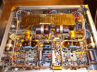
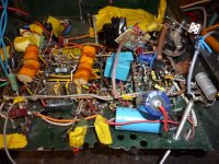
The two pics show for themselves the construction principles.
Still many amp constructors go for the short and dirty of prototyping PTP "birds nest" in a wooden box.
Compare with a pic of a decent PTP, the owner of this amp has taken care and trouble over the locations of parts etc. Centre PCB is heater supply. It is infinitely more reliable than the "birds nest".
Like doing it proper; then show oneself what one is capable of. Like a car; most want to see under the bonnet.
r.
Attachments
In 1957, Juke box manufacturer Seeburg produced two models, KD200 and l100. In previous years, all models were PTP using tubes. Due to the many issues
surrounding cracked circuit paths, caused by heating and cooling, this was the only
year circuit boards were used with tubes. Seeburg continued with circuit boards, after
transistors were used for amplification and control, several years later.
I have an L100 and I think the problem was the materials used for the PCB. I have one that is in good condition and works ok. I find that I have more problems with the connectors then anything. They were way ahead of their time I think.
Sandy
....In the earlier post ..all the carping about that rather discoloured wirewound on the PCB; Here is the reason:-
The place on top side is occupied. A large electrolytic has encroached the footprint area of the resistor; the CAD library incorrect. Anyone should see the electrolytic would have quite a shortened life if the wirewound was "cosying" up to it.
Mistakes like this happen alot of the time even in the best of equipments and where series modifications are done without pad updates.
richy
So the design was bad, not the PCB, if you can't see that a something like this going bad before you do the work on the PCB you likely shouldn't be doing them. Also I can guess that that PCB and likely design was made to be as low cost as possible just due to the 'simulated' double sided board wire jumpers, ie, save money anywhere including the designer.
Doesn't matter what you do if you at least start with common sense and ask for help at DIY AUDIO
I have done PCB for fun for quite a while using PROTEL/ALTIUM pcb software and most of the stuff I have done has been smaller digital based boards.
Doing tube based were somewhat of a challenge at first as it has a very different style to doing a board. To start but the first thing I did was create my own PCB patterns for anything of high heat or have potential for mechanical issues making sure that pads were robust and not default, then be generous with track size and spacing. Time consuming yes, but worth it in the long run.
I'll see how long the boards I did last but I will say that I do like the 2oz copper with the thicker boards. I do like the simplicity of mounting the tube sockets to the PCB but one thing that I make a big effort is to make sure the board has MANY anchor points to the chassis keep things rigid when swapping tubes not just at the corners as I have often seen which I think is a big problem for some designs.
Common sense stuff like that helps keeps you out of some trouble. Mounting anything that generates a lot of heat should have some hole for heat to escape, etc. etc.
And remember PCB's don't kill... people do... wait... is that guns I can never remember that
Use what you like and are comfortable with that's really the bottom line. No shortage of successful projects built with either method.
Sandy
- Status
- This old topic is closed. If you want to reopen this topic, contact a moderator using the "Report Post" button.
- Home
- Amplifiers
- Tubes / Valves
- Point to point or pcb?