ENIG is one of the popular finishes for the exposed pads of PCB's aftre the solderresist has been put on, as it has a good shelf life. Some of the organic finishes now have a good shelf life and with the price of gold, much cheaper. I very rarely use tin or silver, in facft most designs I work on matt tin is an absolute no no, and any lead free BGA's have to be re-balled for the tin lead process.
As to the never ending argument about oxygen free copper, Speedskater kindly provided the shocking figure, regarding resistance.
Thermal management, have a look a COMSOL to see how serious the tools are for thermal design, look around at the expanding world of LED lighting and the thermal issues that have been overcome for these sort of designs.
As to board thickness, go to 2.4 or 3.2mm they will take the hassle, but even 1.6mm boards are tough, its how you mount them thats critical and how the components are fastened down, some designs have to be vibration tested, some have to pass balistics tests, automotive desigsn have to endure extreme temperature ranges and hostile envoironment, as do military and areospace designs, ALL done on PCB's.
I posted a list of some of the IPC specs relevant to PCB's, in the real world the materials, manufacturing techniques, design criteria are always evolving as new challanges are presented, such as high speed design, component density (leading to higher thermal concentrations) ever increasing RF frequencies etc etc, and for all areas of industry PCBs seem to fit the bill perfectly, so why arn't they suitable for audio...
And if you hate second class solutions why use P2P
As to the never ending argument about oxygen free copper, Speedskater kindly provided the shocking figure, regarding resistance.
This shows taht whatever we say or whatever information we provide you have a view in your head that is not going to change. Yet the world runs on PCB's, I work in a PCB design bureau, and funnily enough all our customers want there electronics on PCB's, we even do some audio, though more for the proffesional market. We do a lot of IPC-6011/12 Class 3 designs, if PCB's are good enough for those sort of designs I'm shure we could design an amp on one.Just a sole 6C33 run over 200ºC and big triodes even more; heat management is a small hole or a noisy fan...
I dont know why Iam chating with PCBs guys, I hate second class solutions.
Thermal management, have a look a COMSOL to see how serious the tools are for thermal design, look around at the expanding world of LED lighting and the thermal issues that have been overcome for these sort of designs.
As to board thickness, go to 2.4 or 3.2mm they will take the hassle, but even 1.6mm boards are tough, its how you mount them thats critical and how the components are fastened down, some designs have to be vibration tested, some have to pass balistics tests, automotive desigsn have to endure extreme temperature ranges and hostile envoironment, as do military and areospace designs, ALL done on PCB's.
I posted a list of some of the IPC specs relevant to PCB's, in the real world the materials, manufacturing techniques, design criteria are always evolving as new challanges are presented, such as high speed design, component density (leading to higher thermal concentrations) ever increasing RF frequencies etc etc, and for all areas of industry PCBs seem to fit the bill perfectly, so why arn't they suitable for audio...
And if you hate second class solutions why use P2P
Your into some pretty serious RF work then
I have worked in the same Motorola plant for 40 years. Yeah we do RF, in fact we invented a lot of it.
When I started there we still manufactured one product that had a pair of 12AX7's on a PTP wired chassis. It was designed in the 1960's and was FAA certified for aircraft use. It took about 5 years to get its replacement certified. The replacement was PCB mounted transistors and it started shipping in about 1975. Everything has been PCB ever since.
You remind me of my first HP RF spectrum analyser in 1964....hunk of a beast 5445 or some sim number, a double trayed grey monster using a short-life Watkins-Johnson BWO.....much of this HV analyser was built on ceramic P.T.P.........I flogged the whole lot when I emigrated...What today's folk don't realise, is the amount of radar and the strength of it that was around in the environment in the cold war days. In comparison, my mobile phone struggles to even reach one bar on the scale where I live......
richy
richy
Last edited:
Seems there is alot of PCBs builders in this thread as expected, maybe someone can indicate a ventilation hole in this $140,000 dollars Lamm ML3 large PCB.
If you audio hobbist say you use copper I believe you, but for reduce cost line assembly surely wont use OFC.
.
This LAMM amps shown on your post without top cover, with top cover bodies of all vacuum tubes are still exposed to open air. There is no need for ventilation holes on PCB, I don't know (and don't care) how this amp sounds, but from the point of view of engineering it is properly constructed.
I meausred temperature of similar PCB near power tubes, it is around 80C (176F) after over an hour of continius run at full power (something is not likely to happen).
Member
Joined 2009
Paid Member
I use,
Point to point PCB..Just use plain PCB and solder the tag strip to the copper on the board and use the board as a screen or Gnd...or use Plain PCB without copper coat and mount the tag strip to that..In industry for years they used paxolin board and tag strip for everything from drives to amplifiers..
easy repair if necessary. Mount the tubes through the board with bases and hard wire..its fast and easy or mount the preamp type tubes sideways with angled pieces of aluminium...if you find that it dosen't sound as good as you expected you can use the same shape board again and rewire..soldering and resoldering has little effect...PCB track can lift after resoldering parts or upgrade..Both have advantages..It just depends if you want to spend a few hours making a PCB and then getting annoyed when you have it wrong..
Regards
M. Gregg
For vacuum tube projects, I prefer the point to point approach because mounting tube sockets on a PCB invites reliability problems. Heat and especially inserting/removing tubes stresses the connections, and can result in outright failure, or worse, an intermittent connection problem. If the sockets are chassis mounted and not reliant on the PCB for physical support, then I have no problem with PCBs at all.
The guy from Russian DIY forum sent me a file in .pcb format - PCAD 2006. Which company is better to use to order boards that takes such files?
Hey Wavebourn: this is more of a bump than anything since it didnt get answered, sorry I cant help you with a definite solution. I have no experience with the .pcb format, Gerber is the standard format mainly, you might look to see if you can find a .pcb->Gerber convertor.
since Cadstar reads .pcb files the chance is most large board houses will be able to open it, but they may charge a fee for the process and you may want to check the gerber before they go ahead and use it. you might see if you can convert to gerber for them so you can check it yourself. is it a very complex, large or more than 4 layer design? you may be able to open it in something like Diptrace free
For vacuum tube projects, I prefer the point to point approach because mounting tube sockets on a PCB invites reliability problems. Heat and especially inserting/removing tubes stresses the connections, and can result in outright failure, or worse, an intermittent connection problem. If the sockets are chassis mounted and not reliant on the PCB for physical support, then I have no problem with PCBs at all.
Anyone who has done TV repairs in the 1950's when phenol boards came out for commercials soon realised that HV attracts dust and after a few 1000 hrs operation, tracking faults from householder damp effecting the hydroscopic PCB's were causing instability. The problems were often caused by housewife's steam ironing clothes whilst watching TV in the vicinity, and the fault would disappear when the set was in the service workshop. Good ain'it.
I saw exactly the same in the late 1960's when glass fibre PCB's came in; however, both types of boards enabled tighter component densities and later conformal coating appeared, but the old problem of a standoff wirewound creating heat is just enough to cook the dust and eventually the conformal breaks down.
The old faults, pcb valve sockets, inadequate conductor spacing with HV; are still evident, Yes the last Velleman I repaired had a poorly soldered PCB valve socket pin.
Wave soldering large pins (elect caps) which have a large conductive mass is also an often fault, aggravated in time by thermal expansion. The P.T.P avoids all these.
Viva P.T.P. !!
richy
Last edited:
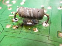
Here is the proof I'm so against PCB's.....this section of a power supply board, failed. The wirewound resistor despite being heat scorched still has the correct resistance; the fault occurred in the copper track which ran under it. After years of expansion/contraction from the heat, the track finally fractured.
Unsuprisingly, many computer aided pcb designs fall right into this trap.
richy
Unsuprisingly, many computer aided pcb designs fall right into this trap.
richy
Attachments
Yes the issues with old cracked/bad solder joints and tube sockets does stain/burn the PCB and really just minor arcing of any kind anywhere is just not good on them, it doesn't take much to blow up and lift a trace lol as well as burning holes through the PCB itself. Some manufactures use a fairly thin board etc P2P has the the advantage as far as reliability in my opinion big deal if a turret eyelet/board blows up or some wires melting relatively inexpensive compared to changing a whole PCB, as far as sound goes it all depends, older P2P designs most had top notch components as well as quality copper/iron but yeah PCB amps are very capable of nice sounds as well, I like the integrated factor of PCB though just feels more organized to me P2P looks like a rats nest but a good rats nest lol.
Depends where at in a certain circuit that trace lifts up if its realatively high voltage and like some circuits in amps there is lower powered circuit right next to it no question about it its gonna jump/arc into them as well and do even more damage on its way to ground lol
I do agree though tube sockets should never be being mounted directly to the PCB, its the not question of if it will cause problems its more like when will it lol.
I had vacuum tube TVs in the past, which worked for a decade. No problems with PCBs.
Now I'm also own some industrial equipment from vacuum tube era, still no problem with PCBs.
Conclusion: do it properly, and it won't last for decades.
Happened to old amp I had and man I tell you it fried all the screen resisters and arced every socket in that sucker lol had some junk Chinese El34s they were only like 2 months old lol they let go apparently and man it sounded like WW3 going on inside lol one of them physically exploded shot glass out the back of the amp the glass stuck in the drywall almost caught the drywall on fire lol
- Status
- This old topic is closed. If you want to reopen this topic, contact a moderator using the "Report Post" button.
- Home
- Amplifiers
- Tubes / Valves
- Point to point or pcb?