You mean say raw copper had zero oxidation like gold??More misinformation?
Gold is named precious metal and is expensive because it had near zero oxidation etc...
My understanding is that refined copper, as used in wires and PCBs, is quite low in oxygen. Getting the oxygen even lower will very slightly reduce the resistance, but this will have no effect on normal electrical uses of copper (including audio). It will add to the cost, though.
It is interesting to reflect that if adding oxygen to copper was an expensive process then it is possible that some people would prefer high-oxygen copper for audio.
It is interesting to reflect that if adding oxygen to copper was an expensive process then it is possible that some people would prefer high-oxygen copper for audio.
Does oxygen free copper realy improve conductivity, and if so by how much, and does it make such a big difference, I wonder, general stuff is cw004a, O free (for use in certain atmospheres and brazing) i cw008A.
As to PCB material, you might be surprised to learn that the whole point of a PCB is to allow current to flow from one device to another, as I have said PCB's are OK for all other areas of electronics, why are they then inferior for audio.
As to PCB material, you might be surprised to learn that the whole point of a PCB is to allow current to flow from one device to another, as I have said PCB's are OK for all other areas of electronics, why are they then inferior for audio.
Now gold wire would look cool, but be very expensive and actually worse than copper
Qusp,
a machined thick copper pseudo PCB (or silver) in a clear polycarnbonate case, with a ebony base would be a work of art, I did do some 3D mock ups, but did it on SolidWorks that I dont have access to any more, nor access to both the raw materials of the enginbeering experience, who were going to do the machining (another subsidury that sufferered from big company reductions). The vias we were3 looking at were M2 copper threaded at bothe ends and screwed in, ground reference plane a solid block of copper.
One day...
Hi,
Sonically which are better amps, ones that are p2p wired or pcb based?
Makes no difference at audio frequencies. P-2-P is better for RF designs as the dielectric is air for greatly reduced stray capacitance. "Dead bug" construction for your RF projects: it goes much faster than having to etch out a PCB, and generally works better.
PCBs are best for mass production as quality is consistent. P-2-P allows for greater flexibility, in that you can always use parts on hand.
A poor lay-out will be a poor lay-out regardless of whether it's a PCB or P-2-P, and can ruin an otherwise good design.
I cant respond this question, but you will no want a PCB amp:
= if the tube is a big triode or 6C33 as these tubes cook the PCB in few time.
Even pre-amps PCBs will be cooked over the years, as a Class A solid state amp;
If the temperature inside your chassis is high enough to cook a PCB, you really need to look at better thermal management.
= PCB tracks never are silver solder, but raw solder or even lead.
You're right. PCB tracks are never silver solder. Or any other kind of solder for that matter. PCB traces are made from copper. If the board house is ROHS compliant, the PCB traces are typically copper with gold plating. If the board house is not ROHS compliant, you'll probably get HAL finish. This is a thin coat of solder on top of the copper traces.
~Tom
Last edited:
PCB with copper tracks is very rare, cause the copper is difficult to melt.
Dude! What are you smoking?!
PCBs with copper traces is what everybody and their dog are using. Take any piece of electronic gear apart and scrape the solder mask (the green coating) off the PCB. Tell me what color the metal is. It's a reddish color. That's COPPER!
I've been making my own PCBs since the mid 1980ies and taken several pieces of gear from the 60ies and 70ies apart. They've all used copper for the traces. In the old days, the dielectric material was paper-based. These days, the cheap stuff is FR-4 (fiberglass).
May I suggest some reading material on the subject:
Printed circuit board - Wikipedia, the free encyclopedia
PCB Manufacturer in Aurora Colorado Manufacturing Annular Ring, Circuit Board Fabrication, Printed Circuit Boards by Advanced Circuits
ExpressPCB - Free PCB layout software - Low cost circuit boards - Top quality PCB manufacturing
https://www.olimex.com/PCB/FAQ/
~Tom
I avoid buy tube amps with PCBs, cause the PCBs usually are big and prevent the proper cooling of the amp.
The fresh air dont pass through the amp, since the PCB blocks the flow of air.
That's why people drill ventilation holes or slots in their PCBs. This is called thermal management.
~Tom
Very well put . Those that I have interacted with in the past that said hand wiring was the only way to go. Some how never built a proper PCB version to compare to the hand wired one . But rather quoted 1950 era data they read about paper based substrate. the teflon boards are far superior to hand wiring for repeatability and the stray cap of the board is of teflon .If only one amplifier is built and if the design is not fully tested, point to point is the only meaningful construction.
Sorry but this is some of the most misinformed comments I have ever seen
There is indeed quite a bit of misinformation here.
yet another reason why pcb is a mystery bag, how thick is it? did the manufacturer use the right glue? will it stand the test of time? should I leave the trace clean or should I lay down half a spool of expensive silver solder?
The PCB designer SPECIFIES what materials he wants, the thicknesses of the copper and the dielectric when he submits the job to the board house. A common double sided PC board uses NO glue in the process. A multilayer board does. It is up to the PC board designer and the board house to get this right.
In 1957, Juke box manufacturer Seeburg.....Due to the many issues
surrounding cracked circuit paths, caused by heating and cooling........
Your cell phone probably has an 8 layer PC board inside it, with about 500 components soldered on it. The manufacturers can crank out millions of them a year. They can make a PC board for a tube amp blindfolded, walking backwards, on their hands. We have come a long way since the junk made in the 50's.
So if a pcb is to be made what would be the recommended copper thickness and board material type.......Standard PCB thickness is 0.062" and 1 oz Copper.
The standard choice for most work is indeed FR4 dielectric, .062 thick with 1oz copper plating. A reasonable choice for final coating is SMOBC with tin plating for the exposed areas. SMOBC means Solder Mask Over Bare Copper. The exposed pads are tin plated for solderability. As stated bare copper will oxidize so it must be covered. The solder mask (green stuff) is sufficient coating. This is the construction that I use for all Tubelab PC boards. They will live for 50+ years even inside a hot vacuum tube amp. A well designed modern PC board will outlast ANY electrolytic cap ever made!
PC boards for computer motherboards are several layers thick, often 6 or 8. The copper thickness can be different on each layer, although the stack up is usually symmetrical to avoid warping. Thin 1/2 or 1 oz copper is used on the layers where a zillion tiny traces are used to connect up the memory and I/O. Thick 2 or 3 oz copper is used to route the power to the hungry processor, memory and PCI connectors. A modern Core i5 processor can draw over 50 AMPS from 1.1 volts to the CPU cores!
PCB with copper tracks is very rare, cause the copper is difficult to melt.
It is possible to make PC boards using a variety of metals, although copper is the most common. I would say that the conductive material in about 99% of all PC boards is copper. The bare copper MUST be covered. There are a variety of precesses for this. a tin / lead solder coating was common until ROHS. Now there are several alternatives including a silver / antimony / tin plating. It is rarely used.
If the board house is ROHS compliant, the PCB traces are typically copper with gold plating.
SMOBC with tin plating IS ROHS compliant. Modern halogen free FR4 is also ROHS compliant. You can't plate gold over copper without a nickle barrier. This construction is used, but isn't common any more due to the cost of gold. There are new alternatives even for Mil Spec boards. Crack open some 60's or 70's Hewlett Packard stuff. All the boards are gold plated.
I design complex PC boards in my full time engineering job. I am currently working on a 14 layer board that is just for a throw away prototype. I am sure that there are still some Sprint / Nextel phones out there with my board designs inside them. I haven't done a phone in 11 years, my collection of old phones still work, if you can find a working battery. There are also quite a few Tubelab amps out there. Anyone ever have a PC board fail? There are some junk PC board based designs out there, but there also some rather poor PTP designs out there too!
the teflon boards are far superior to hand wiring for repeatability and the stray cap of the board is of teflon .
Teflon dielectric is used for microwaves and other applications where low dielectric loss is important. It is not recommended for a tube amp because Teflon is slippery. The adhesion of the copper to the teflon is poor. This will cause copper breakages around the tube sockets when changing tubes. I learned this the hard way. It is possible to laminate teflon board to a conventional FR4 substrate, but it is rather expensive and must be done by a specialty board house. I did have a few made this way for a 2.4 GHz LTE transmitter. Testing revealed that the cost VS performance wasn't justified even in this application.
Last edited:
Does oxygen free copper realy improve conductivity, and if so by how much, and does it make such a big difference, I wonder, general stuff is cw004a, O free (for use in certain atmospheres and brazing) i cw008A.
As to PCB material, you might be surprised to learn that the whole point of a PCB is to allow current to flow from one device to another, as I have said PCB's are OK for all other areas of electronics, why are they then inferior for audio.
From Stephen Lampen's book:
99.95 percent purity would be "three nines" copper .
The difference between "three nines" and "six nines" copper is about 1.5 percent resistance.
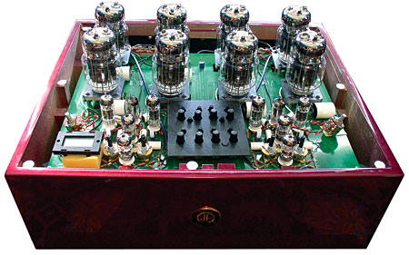
Seems there is alot of PCBs builders in this thread as expected, maybe someone can indicate a ventilation hole in this $140,000 dollars Lamm ML3 large PCB.
If you audio hobbist say you use copper I believe you, but for reduce cost line assembly surely wont use OFC.

Other big PCB no holes:
Just a sole 6C33 run over 200ºC and big triodes even more; heat management is a small hole or a noisy fan...
I dont know why Iam chating with PCBs guys, I hate second class solutions.
If you audio hobbist say you use copper I believe you, but for reduce cost line assembly surely wont use OFC.
Other big PCB no holes:
Just a sole 6C33 run over 200ºC and big triodes even more; heat management is a small hole or a noisy fan...
I dont know why Iam chating with PCBs guys, I hate second class solutions.
Tubelab I must defer on the Pcb to your larger first hand data base on this subject. Had not run in to the trace cracking on tube change using teflon sockets with teflon boards. But then again you have done boards of so many more layer I can't in good faith argue with your findings.
SMOBC with tin plating IS ROHS compliant. Modern halogen free FR4 is also ROHS compliant. You can't plate gold over copper without a nickle barrier.
How about the immersion gold finishes available? Board goes in the soup and comes out gold plated.
I haven't dealt with gold from a PCB manufacturing perspective. But I'm familiar with it from semiconductor manufacturing. It's a PITA to get to stick to anything. As you say, nickel or chromium platings are used as an adhesion layer between the gold and whatever it's supposed to stick to.
Crack open some 60's or 70's Hewlett Packard stuff. All the boards are gold plated.
Yep. Pretty...
~Tom
Tubelab I must defer on the Pcb to your larger first hand data base on this subject.
If you are using a single sided board with the copper on the back, you might be OK. I would still look for some mechanical reinforcement for the socket other than the PCB alone. I have ripped the through holes right out of a teflon board where the tube socket was mounted to the board only. This was the common complaint of the 50's paper or phenolic based PC boards too.
All my designs now mount the tube socket to the board, then screw the board to the chassis. There have been no issues, even in boards that had hundreds of tubes rolled through them. The socket wears out, I change it, then continue on.
That happened about 5 years ago. There are now some teflon composites from Rogers and others that are pretty good, but I haven't tried them. Some have lower loss than Teflon. We had some boards made with ground up ceramic dust imbedded inside for a very high dielectric constant for microwave filters. They couldn't pass our vibration testing, they cracked.
How about the immersion gold finishes available? Board goes in the soup and comes out gold plated.
We have our own board fab in house at work. They can do multilayer board with selective gold plating, but I have never asked how it is done. I rarely use gold on my test boards at work since they are usually destined for the scrap bin after they are used. I make test and application boards for our IC designs.
Gold is used whenever a test probe or other pressure sensitive contact interfaces with the board. Every few years or so I get to do some prototype product designs, we will do a run in house to verify the design, then the proto batch will be built at the board fab that will get the production run.

not just hobbiests, the places where ive gotten boards dont have an option without copper unless its more exotic. the PCB is still designed by someone, the issues you show here are issues with the PCB design, nothing to do with being a PCB. the claims you make of lead traces are the typical uninformed claims made by those wishing to frame PCBs as a global conspiracy to lower costs and suck the life out of audio.Seems there is alot of PCBs builders in this thread as expected, maybe someone can indicate a ventilation hole in this $140,000 dollars Lamm ML3 large PCB.
If you audio hobbist say you use copper I believe you, but for reduce cost line assembly surely wont use OFC.
Other big PCB no holes:
Just a sole 6C33 run over 200ºC and big triodes even more; heat management is a small hole or a noisy fan...
I dont know why Iam chating with PCBs guys, I hate second class solutions.
Tubelab: yes the rogers is very good, Acko uses it for his dacs and I got in on the first run of teflon boards so did all the soldering myself (they come stuffed these days) I didnt have any problem with delamination, pretty hardy really.
Last edited:
If you are running the glass metal seals at over 200 degrees C you are probably doing it wrong, certainally something like a 3/500Z only rates the pin seals to 200 degrees, and the sockets usually run significantly cooler then the seals.
There is however not usually that much heat removed via the pins, so it does not take much cooling to maintain a safe seal temperature, I doubt that it is much of an issue in audio except in very high bias applications, but it can have you in things like grounded grid RF amps with external anode ceramic tubes if you are not careful (I lost more then one 4CX250B before I figured out I was cooking the seals).
PCB is potentially MUCH better electromagnetically then point to point (You cannot really get the loop areas down point to point the way you can with a good pcb layout), so from both a production and electrical quality perspective I would go PCB every time, with the proviso that I might add some mechanical stiffening (or go for a deliberately thick stack up) around heavy parts like tube sockets and any on board magnetics.
Point to point only really wins in things like charge amps where you have Gig ohm impedances and sources producing pC of charge that you are trying to measure, a teflon feedthru, 10Gohm resistor (be careful of fingerprints!) and jfet gate hanging in dry N2 beats a PCB here, but almost nothing in audio is that critical.
Where does the whole OFC thing come from anyway? Most copper for serious electrical applications is ETP which deliberately contains a little oxygen and has exactly the same resistivity as the common grade of OFC.
I dont see how OFC got to be considered so very shiny in the audio game, it seems like mostly smoke, mirrors and marketing woo to me.
Regards, Dan.
- Status
- This old topic is closed. If you want to reopen this topic, contact a moderator using the "Report Post" button.
- Home
- Amplifiers
- Tubes / Valves
- Point to point or pcb?