I am just about to make a Mouser order and thought while I was at it I would get the parts for the schematic in post #122. What is the part number for 74LVC74 on the schematics, I assume it is an eight pin part, as a mouser search for 74LVC74 only shows 14 pin parts with VCC as pin 14.
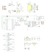
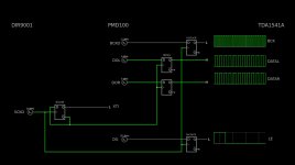
I tried 4x oversampling and found out that there is no different timing: all frequencies stay same from the PMD100, output happens only half as often compared to 8x, so we can simplify the circuit and simulation and use DG of PMD100 to generate LE for the TDA1541A as it's reclocked in any case. The updated code:
Updated schematics attached:
Java:
// for ATtiny84
// pin mapping clockwise
// set clock to 4MHz internal

// works with DIR9001 -> PMD100 -> TDA1541A digital interface board

// change these settings to configure the PMD100:
byte oversampling_rate           =  3; // 1 = 2x oversampling, 2 = 4x oversampling, 3 = 8x oversampling
byte dither_mode                 =  2; // 0~7 = dither mode 0 to 7
byte input_data_justification    =  0; // 0 = left justified, 1 = right justified (16bit)
byte input_bit_clock_polarity    =  0; // 0 = rising edge, 1 = falling edge
byte input_frame_sync_polarity   =  0; // 0 = LRCI high means left channel, 1 = LRCI low means left channel
byte output_word_length          =  0; // 0 = 16bit, 1 = 18bit, 2 = 20bit, 3 = 24bit
byte output_format               =  1; // 0 = 2s compliment, 1 = COB
byte output_word_clock_polarity  =  1; // 0 = high to low at the end of the output word, 1 = low to high at the end of the output word
byte deglitch_low                = 31; // set falling edge of DG to 0~31st interval
byte deglitch_high               = 25; // set rising edge of DG to 0~31st interval
// end of settings

#include <avr/sleep.h>
#include <debouncetm.h>

#define MUTE           0  // MUTE (HIGH = muted)
#define MS1            2
#define MS2            3
#define MS3            4
#define MDT            5
#define MEN            6
#define LED            7  // LED (active HIGH)
#define TOSL          10  // TOSLINK (active LOW with 74LVC125, active HIGH with 74LVC126)
#define COAX           9  // COAX (active LOW)
#define BTN            8  // button pin (HIGH = TOSLINK)

#define samplerate   0.75 // poll interval for update() in msec (a safe starting point would be samplerate = 0.1 * bounce-duration in msec)
#define longpress    0.90 // longpress duration in sec
#define doubleclick  0.50 // doubleclick window in sec
#define history         8 // internal history length: 8, 16 or 32 bit

Button button(BTN, INPUT, HIGH, samplerate, longpress, doubleclick, history);  // specify pin, pinMode, polarity, samplerate, longpress duration, doubleclick window

elapsedMillis sleep_timer;
unsigned int sleep_interval = 500;   // mute ramp down takes 260ms, so 300 is a good value here

void setup() {
  delay(1000);
  pinMode(COAX, OUTPUT);
  pinMode(TOSL, OUTPUT);
  pinMode(MUTE, OUTPUT);
  pinMode(LED, OUTPUT);

  pinMode(MS1, OUTPUT);
  pinMode(MS2, OUTPUT);
  pinMode(MS3, OUTPUT);
  pinMode(MDT, OUTPUT);
  pinMode(MEN, OUTPUT);

  digitalWrite(LED, LOW);
  digitalWrite(MS1, LOW);
  digitalWrite(MS2, LOW);
  digitalWrite(MS3, LOW);
  digitalWrite(MDT, LOW);
  digitalWrite(MEN, HIGH);
  delay(100);
  digitalWrite(MUTE, HIGH);
  digitalWrite(COAX, HIGH);
  digitalWrite(TOSL, LOW);

  delay(100);
  configurePMD100();
  delay(100);
  zeroAttenuationPMD100();
  delay(3000);

  if (!digitalRead(BTN)) {
    digitalWrite(COAX, LOW);
    delay(50);
    digitalWrite(LED, HIGH);
    delay(300);
    digitalWrite(MUTE, LOW);
    delay(300);
  }
  sleep_timer = 0;
}

void loop() {
  button.update();
  if (button.pressed()) {select_TOSL();}
  if (button.released()) {select_coax();}
  if (sleep_timer > sleep_interval) {gotoSleep();}
}

void zeroAttenuationPMD100() {
  digitalWrite(MS1, HIGH);
  digitalWrite(MS2, HIGH);
  delayMicroseconds(1);
  digitalWrite(MEN, LOW);
  delayMicroseconds(1);
  digitalWrite(MEN, HIGH);
  delayMicroseconds(1);
  digitalWrite(MS1, LOW);
  digitalWrite(MS2, LOW);
}

uint32_t value = 0;

void configurePMD100() {
  value = 0;
  value |= uint32_t(dither_mode) << 19;
  value |= uint32_t(output_word_length) << 17;
  value |= uint32_t(input_frame_sync_polarity) << 16;
  value |= uint32_t(deglitch_high) << 11;
  value |= uint32_t(deglitch_low) << 6;
  value |= uint32_t(output_format) << 5;
  value |= uint32_t(output_word_clock_polarity) << 4;
  value |= uint32_t(input_data_justification) << 3;
  value |= uint32_t(input_bit_clock_polarity) << 2;
  value |= uint32_t(oversampling_rate);

  for (int i = 0; i < 24; i++) {
    digitalWrite(MEN, LOW);
    digitalWrite(MDT, bitRead(value, i));
    delayMicroseconds(1);
    digitalWrite(MEN, HIGH);
    delayMicroseconds(1);
  }

  digitalWrite(MDT, LOW);
  delayMicroseconds(4);

  digitalWrite(MS2, HIGH);
  digitalWrite(MS3, HIGH);
  delayMicroseconds(1);

  digitalWrite(MEN, LOW);
  delayMicroseconds(1);
  digitalWrite(MEN, HIGH);

  delayMicroseconds(2);
  digitalWrite(MS2, LOW);
  digitalWrite(MS3, LOW);
}

void select_TOSL() {
  digitalWrite(MUTE, HIGH);
  delay(300);
  digitalWrite(LED, LOW);
  delay(200);
  digitalWrite(COAX, HIGH);
  delay(50);
  digitalWrite(TOSL, HIGH);
  delay(50);
  digitalWrite(LED, HIGH);
  delay(300);
  digitalWrite(MUTE, LOW);
  delay(300);
  sleep_timer = 0;
}

void select_coax() {
  digitalWrite(MUTE, HIGH);
  delay(300);
  digitalWrite(LED, LOW);
  delay(200);
  digitalWrite(TOSL, LOW);
  delay(50);
  digitalWrite(COAX, LOW);
  delay(50);
  digitalWrite(LED, HIGH);
  delay(300);
  digitalWrite(MUTE, LOW);
  delay(300);
  sleep_timer = 0;
}

void gotoSleep() {
  GIMSK |= _BV(PCIE0);
  GIMSK |= _BV(PCIE1);
  PCMSK1 |= _BV(PCINT10);                 // use PB2 as interrupt pin
  // PCMSK0 |= _BV(PCINT4);               // use PA4 as interrupt pin
  ADCSRA &= ~_BV(ADEN);                   // ADC off
  set_sleep_mode(SLEEP_MODE_PWR_DOWN);    // replaces above statement
  sleep_enable();                         // sets the sleep enable bit in the MCUCR register (SE BIT)
  sleep_cpu();                            // sleep
  sleep_disable();                        // clear SE bit
  PCMSK1 &= ~_BV(PCINT10);                // turn off PB2 as interrupt pin
  // PCMSK0 &= ~_BV(PCINT4);              // turn off PA4 as interrupt pin
  ADCSRA |= _BV(ADEN);                    // ADC on
  sleep_timer = 0;
}

// ISR(PCINT0_vect) {sleep_timer = 0;}
ISR(PCINT1_vect) {sleep_timer = 0;}
Updated schematics attached:
Attachments
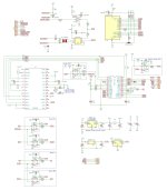
I played around with dither settings and found out that best is to disable dither, so here updated schematics and code:
Java:
// for ATtiny84
// pin mapping clockwise
// set clock to 4MHz internal

// works with DIR9001 -> PMD100 -> TDA1541A digital interface board for Arcam Delta Black Box v1

// change these settings to configure the PMD100:
byte oversampling_rate           =  3; // 1 = 2x oversampling, 2 = 4x oversampling, 3 = 8x oversampling
byte dither_mode                 =  3; // 0~7 = dither mode 0 to 7
byte input_data_justification    =  0; // 0 = left justified, 1 = right justified (16bit)
byte input_bit_clock_polarity    =  0; // 0 = rising edge, 1 = falling edge
byte input_frame_sync_polarity   =  0; // 0 = LRCI high means left channel, 1 = LRCI low means left channel
byte output_word_length          =  0; // 0 = 16bit, 1 = 18bit, 2 = 20bit, 3 = 24bit
byte output_format               =  1; // 0 = 2s compliment, 1 = COB
byte output_word_clock_polarity  =  1; // 0 = high to low at the end of the output word, 1 = low to high at the end of the output word
byte deglitch_low                = 31; // set falling edge of DG to 0~31st interval
byte deglitch_high               = 25; // set rising edge of DG to 0~31st interval
// end of settings

#include <avr/sleep.h>
#include <debouncetm.h>

#define MUTE           0  // MUTE (HIGH = muted)
#define DITH           1  // DITHER (HIGH = on)
#define MS1            2
#define MS2            3
#define MS3            4
#define MDT            5
#define MEN            6
#define LED            7  // LED (active HIGH)
#define TOSL          10  // TOSLINK (active LOW with 74LVC125, active HIGH with 74LVC126)
#define COAX           9  // COAX (active LOW)
#define BTN            8  // button pin (HIGH = TOSLINK)

#define samplerate   0.75 // poll interval for update() in msec (a safe starting point would be samplerate = 0.1 * bounce-duration in msec)
#define longpress    0.90 // longpress duration in sec
#define doubleclick  0.50 // doubleclick window in sec
#define history         8 // internal history length: 8, 16 or 32 bit

Button button(BTN, INPUT, HIGH, samplerate, longpress, doubleclick, history);  // specify pin, pinMode, polarity, samplerate, longpress duration, doubleclick window

elapsedMillis sleep_timer;
unsigned int sleep_interval = 500;   // mute ramp down takes 260ms, so 300 is a good value here

void setup() {
  delay(1000);
  pinMode(COAX, OUTPUT);
  pinMode(TOSL, OUTPUT);
  pinMode(MUTE, OUTPUT);
  pinMode(LED, OUTPUT);

  pinMode(DITH, OUTPUT);
  pinMode(MS1, OUTPUT);
  pinMode(MS2, OUTPUT);
  pinMode(MS3, OUTPUT);
  pinMode(MDT, OUTPUT);
  pinMode(MEN, OUTPUT);

  digitalWrite(LED, LOW);
  digitalWrite(MS1, LOW);
  digitalWrite(MS2, LOW);
  digitalWrite(MS3, LOW);
  digitalWrite(MDT, LOW);
  digitalWrite(MEN, HIGH);
  delay(100);
  digitalWrite(DITH, LOW);
  digitalWrite(MUTE, HIGH);
  digitalWrite(COAX, HIGH);
  digitalWrite(TOSL, LOW);

  delay(100);
  configurePMD100();
  delay(100);
  zeroAttenuationPMD100();
  delay(3000);

  if (!digitalRead(BTN)) {
    digitalWrite(COAX, LOW);
    delay(50);
    digitalWrite(LED, HIGH);
    delay(300);
    digitalWrite(MUTE, LOW);
    delay(300);
  }
  sleep_timer = 0;
}

void loop() {
  button.update();
  if (button.pressed()) {select_TOSL();}
  if (button.released()) {select_coax();}
  if (sleep_timer > sleep_interval) {gotoSleep();}
}

void zeroAttenuationPMD100() {
  digitalWrite(MS1, HIGH);
  digitalWrite(MS2, HIGH);
  delayMicroseconds(1);
  digitalWrite(MEN, LOW);
  delayMicroseconds(1);
  digitalWrite(MEN, HIGH);
  delayMicroseconds(1);
  digitalWrite(MS1, LOW);
  digitalWrite(MS2, LOW);
}

uint32_t value = 0;

void configurePMD100() {
  value = 0;
  value |= uint32_t(dither_mode) << 19;
  value |= uint32_t(output_word_length) << 17;
  value |= uint32_t(input_frame_sync_polarity) << 16;
  value |= uint32_t(deglitch_high) << 11;
  value |= uint32_t(deglitch_low) << 6;
  value |= uint32_t(output_format) << 5;
  value |= uint32_t(output_word_clock_polarity) << 4;
  value |= uint32_t(input_data_justification) << 3;
  value |= uint32_t(input_bit_clock_polarity) << 2;
  value |= uint32_t(oversampling_rate);

  for (int i = 0; i < 24; i++) {
    digitalWrite(MEN, LOW);
    digitalWrite(MDT, bitRead(value, i));
    delayMicroseconds(1);
    digitalWrite(MEN, HIGH);
    delayMicroseconds(1);
  }

  digitalWrite(MDT, LOW);
  delayMicroseconds(4);

  digitalWrite(MS2, HIGH);
  digitalWrite(MS3, HIGH);
  delayMicroseconds(1);

  digitalWrite(MEN, LOW);
  delayMicroseconds(1);
  digitalWrite(MEN, HIGH);

  delayMicroseconds(2);
  digitalWrite(MS2, LOW);
  digitalWrite(MS3, LOW);
}

void select_TOSL() {
  digitalWrite(MUTE, HIGH);
  delay(300);
  digitalWrite(LED, LOW);
  delay(200);
  digitalWrite(COAX, HIGH);
  delay(50);
  digitalWrite(TOSL, HIGH);
  delay(50);
  digitalWrite(LED, HIGH);
  delay(300);
  digitalWrite(MUTE, LOW);
  delay(300);
  sleep_timer = 0;
}

void select_coax() {
  digitalWrite(MUTE, HIGH);
  delay(300);
  digitalWrite(LED, LOW);
  delay(200);
  digitalWrite(TOSL, LOW);
  delay(50);
  digitalWrite(COAX, LOW);
  delay(50);
  digitalWrite(LED, HIGH);
  delay(300);
  digitalWrite(MUTE, LOW);
  delay(300);
  sleep_timer = 0;
}

void gotoSleep() {
  GIMSK |= _BV(PCIE0);
  GIMSK |= _BV(PCIE1);
  PCMSK1 |= _BV(PCINT10);                 // use PB2 as interrupt pin
  // PCMSK0 |= _BV(PCINT4);               // use PA4 as interrupt pin
  ADCSRA &= ~_BV(ADEN);                   // ADC off
  set_sleep_mode(SLEEP_MODE_PWR_DOWN);    // replaces above statement
  sleep_enable();                         // sets the sleep enable bit in the MCUCR register (SE BIT)
  sleep_cpu();                            // sleep
  sleep_disable();                        // clear SE bit
  PCMSK1 &= ~_BV(PCINT10);                // turn off PB2 as interrupt pin
  // PCMSK0 &= ~_BV(PCINT4);              // turn off PA4 as interrupt pin
  ADCSRA |= _BV(ADEN);                    // ADC on
  sleep_timer = 0;
}

// ISR(PCINT0_vect) {sleep_timer = 0;}
ISR(PCINT1_vect) {sleep_timer = 0;}
Attachments

- Home
- Source & Line
- Digital Line Level
- PMD100 to TDA1541 in smultaneous mode