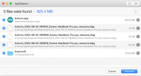
and i made one correction AppCleaner.app does find Arduino15 folder (created bu Arduino.app on the first start) so there is no need for manual delete.
Probaly on the list there could be more items if IDE longer used and with different projects.
.
other Arduino related folder is in the Documents folder BUT that is remains untached and all libraries and projects are still there.
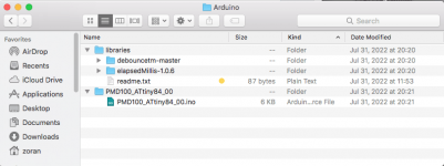
ZIP files (new debounce) for libraries
Arduino - Sketch - Include Library - Add .ZIP library
Probaly on the list there could be more items if IDE longer used and with different projects.
.
other Arduino related folder is in the Documents folder BUT that is remains untached and all libraries and projects are still there.
ZIP files (new debounce) for libraries
Arduino - Sketch - Include Library - Add .ZIP library
Attachments
I listened only in stand alone mode configurations with 8 x OS and factory settings. But it was really rally good. I tried with PCM56, PCM63 and AD1862. As i am remember well it was Riv out with some diskrete BJT darlington output stage. I didnt try with OP amps...
.
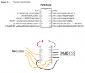
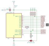
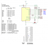
So we need 5 output lines to connect from ATtiny to PMD100.
I suggest to use this pins on ATtiny.
.
Your sketch use some buttons. Probably for selecting inputs (not related to the PMD100)
What is the connections to PMD100 in present way? Schematic of the pins to PMD100 and buttons?
.
So we need 5 output lines to connect from ATtiny to PMD100.
I suggest to use this pins on ATtiny.
.
Your sketch use some buttons. Probably for selecting inputs (not related to the PMD100)
What is the connections to PMD100 in present way? Schematic of the pins to PMD100 and buttons?
Attachments
Last edited:
I use a PMD100 (stand alone mode) with 6 pieces of PCM1702, before that I had a TDA1541 NOS for years and I can say that the PMD100 is a really great filter, no matter how much everyone is cheering for NOS today. I have not tried it with TDA1541, but I am convinced that the result would be better than NOS.Great!
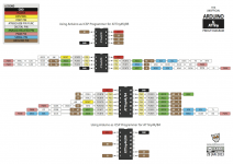
I used this programmer....
Back on topic: how does it sound? What do you think about dither? Should we even disable dither for a 16bit DAC like the TDA1541A?
PMD100 requires a double power supply for best performance, for pin 7 (+5 volt power for filter) a low-noise shunt regulator is mandatory. All these small things affect the sound, although everything is done in the digital domain.
Yes jpk73 but could You post the wiring from AT to PMD? For software mode control? Because I think that last sketch is for that mode?
.
You posted sch for stand alone mode controlled by ATtiny only
like this?
.
You posted sch for stand alone mode controlled by ATtiny only
like this?
Attachments
Last edited:
Yes (it is noted in the PDF of connections Arduino - ATtinyDon't leave the mcu connected to the programmer permanently!
Thanks
.
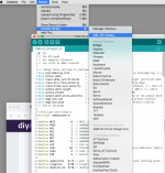
This picture illustrate that sketch is for Programing Mode.
What output pins at the ATtiny84 is from this sim?
MS1 line is missing?
Could You please point to the software for simulating ATtiny You used?
What output pins at the ATtiny84 is from this sim?
MS1 line is missing?
Could You please point to the software for simulating ATtiny You used?
Attachments
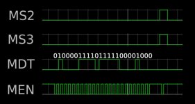
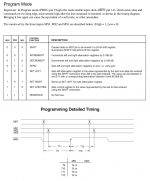
The diagram you quoted in #187 is correct: if you kindly check the pin numbers, they will correspond to the pins used in program mode (MS1 is not needed for setting up the PMD100, only for attenuation reset - see the data sheet for the pin names in stand alone and program mode). Simulation was done here, as all other simulations I showed in this thread...
Thanks for make it more clear ")
So the SCH is for stand alone mode and corresponding pins of PMD100 will remain the same in control mode?
.
I think we have need for MS1. But it is 0 in events on applying MDT?
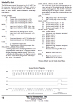
sequence must start with:
SHIFT control function = MS1, MS2 MS3 all "0"
and finishing with:
SET CONTROL MS1="0", MS2 MS3="1" like in Your sim.
So the MS1 pin in program mode, could be connected to GND "0" because for these events is always "0"?
.
Did You said that attenuation reset has to be done before setting all
So the SCH is for stand alone mode and corresponding pins of PMD100 will remain the same in control mode?
.
I think we have need for MS1. But it is 0 in events on applying MDT?
sequence must start with:
SHIFT control function = MS1, MS2 MS3 all "0"
and finishing with:
SET CONTROL MS1="0", MS2 MS3="1" like in Your sim.
So the MS1 pin in program mode, could be connected to GND "0" because for these events is always "0"?
.
Did You said that attenuation reset has to be done before setting all
Attachments
Yes I know that online simulator
but it is not for Arduino code and that stuff to check.
So You emulated just sequence in time translated from the skatch?
.
I found some Arduino boards online sims
https://www.digikey.com/en/maker/bl...r-hobbyists-makers-and-classroom-environments
but something is always the hidden catch, leading for restrict usage.
makecode dont have main and most use Arduino boards
wokwi does not allowing to import libs - it is not free
I didnt get to third tinkercad
.
why it is everything with MCs so confusing, complicated and hidden. shame...
Last edited:
Hi
I checked and compared IDE sketch, variables, mapping and physical pins.
.
I checked and compared IDE sketch, variables, mapping and physical pins.
.
//
// for ATtiny84
// pin mapping clockwise
// set clock to 4MHz internal
//
// group ATtiny PMD100
// map port 44/84
//
// MUTE 0 = PA0 = pin 13 = pin 15
// PROG 1 = PA1 = pin 12 = pin 9
// MS1 2 = PA2 = pin 11 = pin 10
// MS2 3 = PA3 = pin 10 = pin 11
// MS3 4 = PA4 = pin 9 = pin 12
// MDT 5 = PA5 = pin 8 = pin 13
// MEN 6 = PA6 = pin 7 = pin 14
// LED 7 = PA7 = pin 6
//
// group
// arduino
//
// TOSL 10 = 10 = pin 2
// COAX 9 = 9 = pin 3
// BTN 8 = 8 = pin 5
//
#define MUTE 0 // MUTE (HIGH = muted)
#define PROG 1 // HARDWARE MODE: LOW
#define MS1 2 // HARDWARE MODE: LOW
#define MS2 3 // HARDWARE MODE: LOW
#define MS3 4 // HARDWARE MODE: LOW
#define MDT 5 // HARDWARE MODE: LOW
#define MEN 6 // HARDWARE MODE: LOW
#define LED 7 // LED (active HIGH)
#define TOSL 10 // TOSLINK (active LOW with 74LVC125, active HIGH with 74LVC126)
#define COAX 9 // COAX (active LOW)
#define BTN 8 // button pin (HIGH = TOSLINK)
//
Attachments
Last edited:
OK i will note this.
thanks for giving the chance to learn something new and usefull.
btw i am not all out from programming but say i am the old school from 85 learning fortran, cobol, etc.
theese days i am almost using matlab and matcad...
.
Say why do You used this complicated method for putting together 24 bit MDT word?
first you take decimal number to 8bit binarry value, and latter you cutting out unwanted bits and merging the whole word?
.
This first method of defining in one line MDT word is OK too and have clear refference to the datasheet?
I am not criticizing just think loud...
// change these settings to configure the PMD100:
byte oversampling_rate = 3; // 1 = 2x oversampling, 2 = 4x oversampling, 3 = 8x oversampling
byte dither_mode = 2; // 0~7 = dither mode 0 to 7
byte input_data_justification = 0; // 0 = left justified, 1 = right justified (16bit)
byte input_bit_clock_polarity = 0; // 0 = rising edge, 1 = falling edge
byte input_frame_sync_polarity = 0; // 0 = LRCI high means left channel, 1 = LRCI low means left channel
byte output_word_length = 0; // 0 = 16bit, 1 = 18bit, 2 = 20bit, 3 = 24bit
byte output_format = 1; // 0 = 2s compliment, 1 = COB
byte output_word_clock_polarity = 0; // 0 = high to low at the end of the output word, 1 = low to high at the end of the output word
byte deglitch_low = 15; // set falling edge of DG to 0~31st interval
byte deglitch_high = 31; // set rising edge of DG to 0~31st interval
// end of settings
uint32_t value = 0;
void configurePMD100() {
value = 0;
value |= uint32_t(dither_mode) << 19;
value |= uint32_t(output_word_length) << 17;
value |= uint32_t(input_frame_sync_polarity) << 16;
value |= uint32_t(deglitch_high) << 11;
value |= uint32_t(deglitch_low) << 6;
value |= uint32_t(output_format) << 5;
value |= uint32_t(output_word_clock_polarity) << 4;
value |= uint32_t(input_data_justification) << 3;
value |= uint32_t(input_bit_clock_polarity) << 2;
value |= uint32_t(oversampling_rate);
for (int i = 0; i < 24; i++) {
digitalWrite(MEN, LOW);
digitalWrite(MDT, bitRead(value, i));
delayMicroseconds(1);
digitalWrite(MEN, HIGH);
delayMicroseconds(1);
}
first you take decimal number to 8bit binarry value, and latter you cutting out unwanted bits and merging the whole word?
Originally I used 8bit words as for the PMD200, just kept the same concept. Also to make it easy for the user to change settings instead of manually assembling the 24bit word. Easy for debug as well: just print out the 24bit word to serial monitor and check if it matches the data sheet. Do you have a better idea?
I dont know maybe sometning like You did in the first posted sketch?
starting with
//
// 24bit value for PMD100:
unsigned long value = 0b010000011111111100001000; // OS = 4x, dither mode = 2
//
void clockout(byte val) {
for (int i = 0; i < 8; i++) {
digitalWrite(menPin, LOW);
delayMicroseconds(1);
digitalWrite(mdtPin, !!(val & (1 << (7 - i))));
delayMicroseconds(1);
digitalWrite(menPin, HIGH);
delayMicroseconds(2);
}
//
I see, but 0b010000011111111100001000 is not so easy to configure for most people, and I got it wrong (as I said multi bit fields are LSB in contrary to the PMD200)... Also in the first sketch I divided the 24bit into 3x 8bit, so not really simple as well. I will stick to the more convenient method of my last version...
BTW I never learnt to program apart from a few lessons in GWBASIC in the 80's
BTW I never learnt to program apart from a few lessons in GWBASIC in the 80's
Yes but when the word is already formed
you can load it as 24 bit like in second example?
unsigned long MDTbits = 0b010000011111111100001000;
for (int i = 0; i < 24; i++) {
digitalWrite(MDT, bitRead(MDTbits, i));
}
.
I persume that You want to avoid IF THAN steps
.
Maybe to try with
ok hmm...
.
never mind second example is also very good.
you can load it as 24 bit like in second example?
unsigned long MDTbits = 0b010000011111111100001000;
for (int i = 0; i < 24; i++) {
digitalWrite(MDT, bitRead(MDTbits, i));
}
.
I persume that You want to avoid IF THAN steps
.
Maybe to try with
BTW I never learnt to program apart from a few lessons in GWBASIC in the 80's
ok hmm....
never mind second example is also very good.
- Home
- Source & Line
- Digital Line Level
- PMD100 to TDA1541 in smultaneous mode