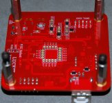
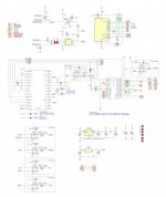
Final working version:
View attachment 1046969
Schematic as of #103 but with C7, C8, R9, R10, R12, R13 deleted. Sounds great!
Dear jpk73:
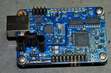
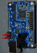
Do you know if it´s possible to use a WaveIo or JLsounds USB boards in the Arcam BB DAC?
I removed some parts that take control of the digital circuit, connect the DATA, BCLK and LRCLK but I have no sound at all from none of these USB boards!
If I use a SPDIF board with DIR9001 I´ve got sound at first attempt!
Many thanks in advance for your help!
Attachments
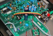
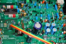
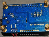
Yes, the GND ins connected and digital (DATA) mute transistors are removed - as shown in the last pic.
What intrigues me the most is that I have the Black Box playing music very very well with the SPDIF DIR9001 card (clean, detailed, natural, focused), and no sound if I connect the DATA, BCKL, LRCK and GND lines on a JLsounds or the WaveIo USB card.
Any help will be greatly appreciated.
Thank you!
What intrigues me the most is that I have the Black Box playing music very very well with the SPDIF DIR9001 card (clean, detailed, natural, focused), and no sound if I connect the DATA, BCKL, LRCK and GND lines on a JLsounds or the WaveIo USB card.
Any help will be greatly appreciated.
Thank you!
Attachments
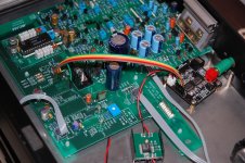
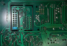
Well...in my opinion everything is as it should, but no sound at all with none of these USB boards. What a what a paranormal situation!
Attachments
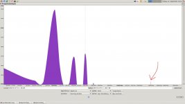
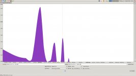
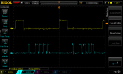
I found a stupid mistake in the schematic: the inverter in the EMPH line between the DIR9001 and the PMD100 needs to be removed. Also I managed to simplify the glue logic thanks to program mode of the PMD100 by using DG instead of WCKO to create LE. In the Arduino sketch set deglitch_high = 25 and deglitch_low = 31 in order to get the DG timing right. The result is shown in attached scope shot: yellow is LE, blue is DATA(R).
Attachments
@jpk73 is that entire up to date schematic of PMD filter?
Yes!
Waking this thread again.
I'm about to be gifted a working cd-player with PMD100 and two PCM63's.
I was hoping the input board could use wm8804/8805 as I have a few of those. I thinkI have a pair of DIR9001 as well.
I'd like to design a board for spdif in and make the output compatible with both PCM63's and TDA1541A.
I'm about to be gifted a working cd-player with PMD100 and two PCM63's.
I was hoping the input board could use wm8804/8805 as I have a few of those. I thinkI have a pair of DIR9001 as well.
I'd like to design a board for spdif in and make the output compatible with both PCM63's and TDA1541A.
If you plan to pull the chips from that CD-Player and use them for your own DAC you can use the information in this thread for DIR9001 into PMD100 into TDA1541A. PCM63 can directly be connected to PMD100, so you don't need the glue logic inbetween the PMD100 and the TDA1541A for the PCM63.
I don't know if I'll pull the PMD100 and two PCM63's, or if I'll re-cap the CD-player and try to fit an SPDIF input tbh.If you plan to pull the chips from that CD-Player and use them for your own DAC you can use the information in this thread for DIR9001 into PMD100 into TDA1541A. PCM63 can directly be connected to PMD100, so you don't need the glue logic inbetween the PMD100 and the TDA1541A for the PCM63.
I've long ago made backups of my CD's to a NAS for access from Moode Audio.
So, I'm thinking about designing a PCB for the DIR9001 & PMD100(and maybe optional glue logic with onboard switches to bypass the glue logic if possible), and separate PCB for the PCM63's (I have PCB's for TDA1541A).
Does that sound like it would work? Using U.FL connectors and cables for the signals between boards.
- Home
- Source & Line
- Digital Line Level
- PMD100 to TDA1541 in smultaneous mode