ZP,
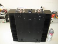
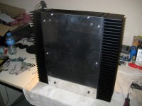
what's the reasoning behind the completely open bottom panel and the (odd attached) sub-chassis ?
sub-chassis is necessary because the housing's of rigidity and assembly power supply. Also, it is implemented because used components are available for fix or upgrade.
(Most effective way to cool electrolytics is at the ends, btw. Some folks even use thermal goop, in particular with stud/nut mount cans)
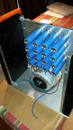
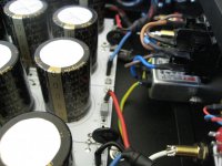
You have probably thought about "white capacitors". They are not electrolytes already they are motor-run 50uF capacitors.
Attachments
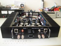
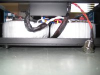
Here's my F5T v2. Still need to tie down the wiring.
Very powerful!

260k+ uF per channel. Two 11 amp toroid's.
And CMC RCAs!")
Looks good Vince.
Hopefully no problems this time.
Nash

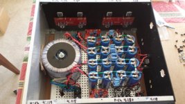
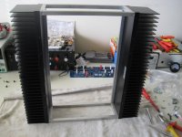
And the last, F5 classic, power supply is dual-mono, 2x150VA 33mF-0,47-33mF. Housing is DIY.
More photos by phases of construction:
housing construction
assembly housing
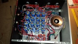
assembly and testing
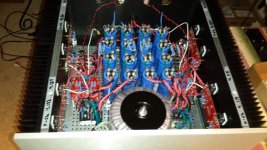
Finish
That's all,
regard
P.S. I apologize for spelling errors, blame google
Zocky, love your constructions! Very inspirational work for me...
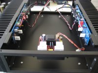
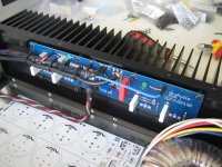
Aleph J in new chassis
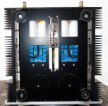
Because I like the Aleph J much and it deserved to be biased higher, I made a new chassis. Old chassis was a standard 3U 300mm.
It uses 4 x 0.4K/W heatsinks, which can handle the heat of the Aleph J when the MOSFETs are biased around 30 Watt each.
I removed R27: the 68k2 and the 100k trimpot. so they are fully biased now around total of 2.5 Ampere class A
Also upgraded some components, MPC74 source resistors, 1837 type 100nF bypass of the 220uF and new better European NTC's in series in the softstart.
The originals blew in my F5T build.
For the power supply I used the BYW99-200 diodes from Jacco, boards from Teabag and Nichicons in the last row of the PSU.
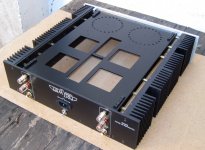
Next is to design a nice front plate and top plate.
I'm listening to it now and it is a good overall amplifier, but at this moment I like my CSX-1 Sony VFET the most... maybe Aleph J needs some more hours of burn in.
Next amp is again with Sony VFETs, if Pa publishes new article with a matched pair in output stage
Because I like the Aleph J much and it deserved to be biased higher, I made a new chassis. Old chassis was a standard 3U 300mm.
It uses 4 x 0.4K/W heatsinks, which can handle the heat of the Aleph J when the MOSFETs are biased around 30 Watt each.
I removed R27: the 68k2 and the 100k trimpot. so they are fully biased now around total of 2.5 Ampere class A
Also upgraded some components, MPC74 source resistors, 1837 type 100nF bypass of the 220uF and new better European NTC's in series in the softstart.
The originals blew in my F5T build.
For the power supply I used the BYW99-200 diodes from Jacco
, boards from Teabag and Nichicons in the last row of the PSU.Next is to design a nice front plate and top plate.
I'm listening to it now and it is a good overall amplifier, but at this moment I like my CSX-1 Sony VFET the most... maybe Aleph J needs some more hours of burn in.
Next amp is again with Sony VFETs, if Pa publishes new article with a matched pair in output stage
Attachments
-
 A10.jpg433.9 KB · Views: 752
 -
 A9.jpg511.4 KB · Views: 758
 -
 A8.jpg229.9 KB · Views: 856
 -
 A7.jpg338.6 KB · Views: 902
 -
 A11.jpg427.2 KB · Views: 777
 -
 A6.jpg332.3 KB · Views: 1,373
 -
 A5.jpg397.7 KB · Views: 1,402
 -
 A4.jpg477.1 KB · Views: 1,401
 -
 A3.jpg300.1 KB · Views: 1,443
 -
 A2.jpg291.6 KB · Views: 1,516

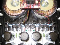
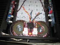
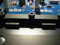
just be sure to not make any sort of short between two Donuts central screws
I pressume they're on chassis bottom - non isolated- and I see red pcb on some sort of platform
You are right, haven't really thought about that..... but there is around 5mm between the donut metal plates and the aluminum platform.
It gives no sparks during start-up
Attachments
You are right, haven't really thought about that..... but there is around 5mm between the donut metal plates and the aluminum platform.
It gives no sparks during start-up
buy two adequate sized Rotring radierer gummi , and glue them in between Donuts and platform
ya know how gummi is important for safety ....

- Home
- Amplifiers
- Pass Labs
- Pictures of your diy Pass amplifier