Today the enclosure arrived! Here some pics of my B1 build
Why did you use a case with heatsinks?
Heat sinks
Well, no reason at all other than looks. I have Class A amp with the same enclosure type. So this one goes under the Class A amp
Just looks better to have the same type of enclosure
Why did you use a case with heatsinks?
Well, no reason at all other than looks
. I have Class A amp with the same enclosure type. So this one goes under the Class A amp Just looks better to have the same type of enclosure
Well, no reason at all other than looks
Just looks better to have the same type of enclosure
It surprise me that you use a very high end rotary switch (ELMA, right?) to control the relays. Is not a bad idea at all, just that the point of using a relay board is to short signal cables lenght and be able to use cheap switches.

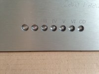
Switch
The reason for that is the following: I need 7 inputs. The switchboard has 6. The CD input will go directly through the switch.
It surprise me that you use a very high end rotary switch (ELMA, right?) to control the relays. Is not a bad idea at all, just that the point of using a relay board is to short signal cables lenght and be able to use cheap switches.
The reason for that is the following: I need 7 inputs. The switchboard has 6. The CD input will go directly through the switch.
Fancy parts
I don't have the skill or the tools to make my own boards. So I have to do it this way. The PSU was allready bought so no need to buy an extra one If anyone can give me good and solid advice regarding layout and wiring, I would love to hear it! I'm new at this! The boards can go anywhere.... so any help is valued I could even only use the switch.... The selector board didn't cost much and I love the idea of nice blue leds But if the board is a bad idea I can discard easally.....
Fancy parts are more important than layout
let alone schematic
( and relays really like best switching ; remember all those Elektor preamps , with drekload of logic for 5 relays , and mediocre audio circ)
I don't have the skill or the tools to make my own boards. So I have to do it this way. The PSU was allready bought so no need to buy an extra one
If anyone can give me good and solid advice regarding layout and wiring, I would love to hear it! I'm new at this! The boards can go anywhere.... so any help is valued I could even only use the switch.... The selector board didn't cost much and I love the idea of nice blue leds But if the board is a bad idea I can discard easally.....Location
Hi Jacco,
I get it.... again, new at this. That board should be near the inputs right?
Maybe I should just use the Elma input switch? It's a 3 pole 7 pos switch so I could use the 3rd pole for switching LED's....
Better Jacco?
The location of the relay board is no surprise ?
Hi Jacco,
I get it.... again, new at this. That board should be near the inputs right?
Maybe I should just use the Elma input switch? It's a 3 pole 7 pos switch so I could use the 3rd pole for switching LED's....
Better Jacco?
Sinks
Hi Walter,
You are absolutely right! Bus I chose the exact same one as my Class A amp Just for looks.....
Hi Sjoerd, why do you have sinks? A galaxy maggiorato from modushop is much cheaper...
It looks nice though
Hi Walter,
You are absolutely right! Bus I chose the exact same one as my Class A amp
Just for looks.....switch
Hey, I love relays.
The LEDs really don't mind lengthy wires from the back to the front panel, a flat ribbon cable will do.
we must first make some fun , then give advice
nature of the beast , I suppose
relay pcb ditto to input connectors
then active electronic to it
attenuator - near relay pcb , with extending shaft to front button
buy cheapest (close or open case, irrelevant) switch for relay commanding , save Elna for something later
look here for some insight of , say , good layout : AVC & Input Selector for Papa’s Koan M2 ; temporary case ? | Zen Mod Blog
even , when using AVC attenuator ( instead of resistive one ) some other things are dictating layout - possibility of easy manipulation with xformers - they need re-stacking , at least once , to make them sing in best way ; that's why wires are longer than needed , usually
that's really just quickie , made of parts I had laying around , including the case
Last edited:
Guys,
I have been thinking about how to set up the components.Thank for all your tips!
I need 7 inputs, so discarding the Elma switch is not an option. Now here's my idea: I am going to get rid of the relay board and will use the Elma 3 pole 7 pos switch for the signal. The 3rd pole will be used to power the led's. I will get the power for the led's from the PSU's led's.
The attenuator and position switch will be positioned very near to the rear...(thanks for the tip Zen Mod) The signal wires are going to be as short as possible that way.
What do you think?


we must first make some fun, look here for some insight
With all the hairy wiring, considered naming it the BlowTurd ?
- Home
- Amplifiers
- Pass Labs
- Pictures of your diy Pass amplifier