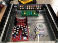
Main PCB
You mean the B1 PCB closer to the PSU?
pull main pcb slightly to fron , place both selector and vol ditto to input RCAs
You mean the B1 PCB closer to the PSU?
I would place right next to the input connectors the relay board. And the B1 board next to the volume control. Then run wires from inputs to switching board, and from switching board to volume control. Then the output of the volume control to the B1 board, which would be sitting right next to the volume control. Then output of the B1 board would run again to the back of the amp, to the output connectors.You mean the B1 PCB closer to the PSU?
Anyone else thinks this should be the more logical arrangement?
Ant the PSU would be optimal as close as possible to the B1 board, but being careful to not cross signal wires with transformer and power cables, mainly the AC ones.You mean the B1 PCB closer to the PSU?
I get the picture(s)
But this is going to be near to impossible.... I cannot find rod extenders that go around corners greater than 15 degrees.... So I have to put the pot and the switch on the sides because that is where the holes in the frontpanel are......This cannot be changed anymore....
But this is going to be near to impossible.... I cannot find rod extenders that go around corners greater than 15 degrees.... So I have to put the pot and the switch on the sides because that is where the holes in the frontpanel are......This cannot be changed anymore....
Last edited:
(Just my opinion) I don't really care about rod extenders, if you dont cross your signal wires with AC power wires or someting that can make any interference, you shouldn't have any proble with that. You probably have already some addittional feet of signal wire before coming into the preamp. Use a shielded wire for that and leave the volume attenuator as it is.I get the picture(s)
But this is going to be near to impossible.... I cannot find rod extenders that go around corners greater than 15 degrees.... So I have to put the pot and the switch on the sides because that is where the holes in the frontpanel are......
yup - I forgot that first picture , had in mind that you're going to make own holes on FP
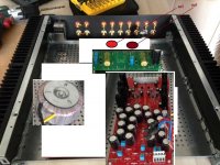
however - if number of inputs permits , then use relay board (ditto to RCAs) , volume through extending rod in most right corner near RCAs , and in most left front corner - cheap switch for relay select
B1 pcb right to relay pcb
PSU pcb right in front of B1
Donut behind switch
however - you dig your own , choosing that case
 obviously
 Layout
Ok idea :
:
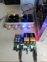
I mount the relay board "over" the inputs on the back panel. That way, the input wires are really short. Then the B1 board a little bit more to the front so the attenuator is really close to it.
The output of the relay board will go to the attenuator and the output of the attenuator to the input of the B1, as RegiRegi22 sugested.
I will use a cheap selector switch(it was supplied with the relay board) and I will go for only 6 inputs.
Any thoughts on this?
Ok idea
:I mount the relay board "over" the inputs on the back panel. That way, the input wires are really short. Then the B1 board a little bit more to the front so the attenuator is really close to it.
The output of the relay board will go to the attenuator and the output of the attenuator to the input of the B1, as RegiRegi22 sugested.
I will use a cheap selector switch(it was supplied with the relay board) and I will go for only 6 inputs.
Any thoughts on this?

I think this should be a good arrangement, any chance to post a picture with the boards and transformer in the case as they will finally be placed?Ok idea
I mount the relay board "over" the inputs on the back panel. That way, the input wires are really short. Then the B1 board a little bit more to the front so the attenuator is really close to it.
The output of the relay board will go to the attenuator and the output of the attenuator to the input of the B1, as RegiRegi22 sugested.
I will use a cheap selector switch(it was supplied with the relay board) and I will go for only 6 inputs.
Any thoughts on this?
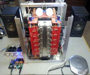
A Six Pak 4 6L6
Just finished and hooked up the O2 headphone/pre to the BA-3. Simply gorgeous! The amp has never sounded so good. Very spacious and defined. There is absolutely no hum or any other sound/coloration I can detect so far with the O2 volume at max. There are two gain settings, and even at low there is all the boost I needed to drive the lowish efficiency Sunflower speakers. Didn't need much but there is more that I would normally use. The high setting will probably allow my neighbors to hear what I hear.
IMHO - a fantastic aid that preserves what the Pass amps are all about. When I finally get around to finalizing the chassis the O2 may well end up inside, It was a very high grade kit with all components clearly identified.
TNX Mr.6
Attachments
Last edited:
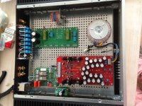
It's a good idea if you mount the board close to the heatsink, as further as possible form the softstart board. Now that's a layout I like, I like it very much. Very good idea to mount the relay input board on the back panel.good now
though - you can still rotate main pcb for 90 , to have both channels equally close to relay pcb
I have used that softstart boards, they are pretty good ones. From that swedish guy, what was his name, something like Sjostrom?
- Home
- Amplifiers
- Pass Labs
- Pictures of your diy Pass amplifier