This shows something like you should see on either pin 5 or pin 8.
Notice how the notional centre line is biased to 1.5 volts. This allows the sine to swing up to +3 volts (your supply) and down toward zero.
So we have here a peak voltage of 1.2 volts and peak to peak of 2.4 volts. The rms value is Vpeak*square root of 2 so that becomes 1.2*1.414 which is 1.7 volts.
On your amp, because the speaker is driven by two antiphase signals it would see in this example 2.4 volts peak and so the rms value becomes 2.4*1.414 which is 3.4 volts. That would be a power of 1.4 watts rms into 8 ohm.
Before i start again you are helping me so much, thank you!
")
So the power is 1.4 watts. So i bought wrong speakers again?
Also i got a multimeter not a scope. I'm not English so i thought a scope was a multimeter sorry :|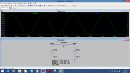
Before i start again you are helping me so much, thank you!
So the power is 1.4 watts. So i bought wrong speakers again?
Its no problem
and it might make more sense seeing it drawn as a scope trace.So with your meter, whatever AC voltage you measure across the speaker is the rms value. You multiply that by itself and divide by 8 (ohms) to get the power.
For example 28.3 volts rms is 100 watts into 8 ohms. Change the load to 2 ohms and would be 400 watts and so on.
Have to leave it for today.
Its no problem
So with your meter, whatever AC voltage you measure across the speaker is the rms value. You multiply that by itself and divide by 8 (ohms) to get the power.
For example 28.3 volts rms is 100 watts into 8 ohms. Change the load to 2 ohms and would be 400 watts and so on.
Have to leave it for today.
Okay i will try to understand this, thank you again
I'm sure you are doing this but just make sure you are using an AC volts range on the meter for measuring these values.
I think so it says VAC. Also across the speakers is one pin on the one side and one pin on the other right?
I think so it says VAC. Also across the speakers is one pin on the one side and one pin on the other right?
Easy one first, yes that's correct.
This shows something like you should see on either pin 5 or pin 8.
Notice how the notional centre line is biased to 1.5 volts. This allows the sine to swing up to +3 volts (your supply) and down toward zero.
So we have here a peak voltage of 1.2 volts and peak to peak of 2.4 volts. The rms value is Vpeak*square root of 2 so that becomes 1.2*1.414 which is 1.7 volts.
On your amp, because the speaker is driven by two antiphase signals it would see in this example 2.4 volts peak and so the rms value becomes 2.4*1.414 which is 3.4 volts. That would be a power of 1.4 watts rms into 8 ohm.
I thought this didn't sound right when I typed it.
1.2 volts peak is 0.848 vrms (its divided by root2, not multiply). That would be what you would see on a conventional single amp.
Now for your bridged amp that becomes double that or 2.4 volts peak and 1.7vrms.
1.7 vrms develops 0.36 watts rms into 8 ohm. That's the maximum power available.
Sorry about that.
To increase 5 volts to 8.4 (or another voltage) you need a switching type power supply. Lots of ways to do that although pure diy from scratch won't be very easy.
Boost converter - Wikipedia, the free encyclopedia
Chip manufacturers will have worked examples and probably even evaluation boards available.
You can also buy off the shelf small switching convertors, say 5 volt to 9 or 12 volt and so on. Connecting batteries (to charge them ?) involves more than just connecting them to a voltage source... if that's what you are thinking.
Back in a bit You need a step up type reg to convert 5 to something higher than the battery voltage and then a charge circuit to supply the battery.
This kind of thing just as an example... not what to use.
TME 0509S | 1W Isolated DC-DC Converter, Vin 4.5 → 5.5 V dc, Vout 9V dc, 1000V dc | TRACOPOWER
You need a step up type reg to convert 5 to something higher than the battery voltage and then a charge circuit to supply the battery.This kind of thing just as an example... not what to use.
TME 0509S | 1W Isolated DC-DC Converter, Vin 4.5 → 5.5 V dc, Vout 9V dc, 1000V dc | TRACOPOWER
You're going to have to look at the battery technology and requirements. I'm guessing your going for Li-On batteries which mean you have to follow the manufacturers directions carefully. NiMH and NiCad are much more forgiving. Don't underestimate how much current a Li-On type may want to draw on its main charge sequence.
The easy answer that covers 95% of cases is yes, and to justify that by adding that its OK as long as there are no ground conflicts... in other words the battery negative connects to the charger minus terminal (so isn't floating).
Okay, thank you.
- Status
- This old topic is closed. If you want to reopen this topic, contact a moderator using the "Report Post" button.
- Home
- Design & Build
- Parts
- Picking out parts for this schematic