Excellent
And well done !
Thank you so much your the best!
Thanks, and you're very welcome.
So today my new speakers arrived (28mm Ø) The sound is better but it is still some distorted at high volume :| Is it possible to fix that? Its only when its 75%-100% of volume.
Depends on the cause. Again, the scope tells you so much when looking for problems like this. Possible causes, you are simply overdriving the amp such that the output has reached the limits of the supply and can swing no higher, the speaker impedance (which varies considerably at AC) is causing to much current draw and the chip is entering some limiting mode or, perhaps some form of instability sets in as output voltage swing increases (definite scope territory to diagnose that).
Depends on the cause. Again, the scope tells you so much when looking for problems like this. Possible causes, you are simply overdriving the amp such that the output has reached the limits of the supply and can swing no higher, the speaker impedance (which varies considerably at AC) is causing to much current draw and the chip is entering some limiting mode or, perhaps some form of instability sets in as output voltage swing increases (definite scope territory to diagnose that).
Okay. The speaker i bought was 8 Ohms and 0.5w. The other speaker i tested it on is also 8 Ohms but 100w and the sound there is so high and clear. Is that telling you something that can there can be a problem with the power that the speaker gets?
Well small speakers do have limited power handling. If you are running the speaker in free air then the cone can easily reach the limits of its excursion and hit the end stops causing horrible (mechanical) distortion. Speakers with airtight loading (mounted in a cabinet or on a large baffle) behave much better because the cone is pushing on a fixed airspace which is hard to push against.
A 0.5 watt 8 ohm speaker means that the most it can handle is 2 volts rms. That's less than 6 volts peak/peak.
Small speakers tend to be acoustically inefficient compared to large ones meaning that the apparent sound is much lower for a given input voltage.
Also, a small speaker will have a limited frequency range at the lower end and so if you are feeding it the full bandwidth then the cone tries to move on the large bass notes, hits the end stops and distorts. There is no actual sound produced because the small cone isn't moving the air properly, all it does is distort.
Normally it means chassis ground but they chose the wrong symbol here. They mean signal/power ground.Lol, wrong
It means a chassis ground that isn't necessarily connected to a mains ground. It is a subtle difference. Ground symbols tend to get misused... we think we know what they mean and then realise we used the wrong one.
It is actually a battery symbol and they mean a variable voltage. The picture (where the symbols come from) is a test circtuit (the usual name for this) but they call it "measurement circuit" and this is often not the real circuit for a design.1/ A variable capacitor. You wont find those in audio stuff. They are for tuning RF circuits (typically)
Well small speakers do have limited power handling. If you are running the speaker in free air then the cone can easily reach the limits of its excursion and hit the end stops causing horrible (mechanical) distortion. Speakers with airtight loading (mounted in a cabinet or on a large baffle) behave much better because the cone is pushing on a fixed airspace which is hard to push against.
A 0.5 watt 8 ohm speaker means that the most it can handle is 2 volts rms. That's less than 6 volts peak/peak.
Small speakers tend to be acoustically inefficient compared to large ones meaning that the apparent sound is much lower for a given input voltage.
Also, a small speaker will have a limited frequency range at the lower end and so if you are feeding it the full bandwidth then the cone tries to move on the large bass notes, hits the end stops and distorts. There is no actual sound produced because the small cone isn't moving the air properly, all it does is distort.
I now got a scope. What should i test?
I want to test how many mW the amplifier outputs. Should i messure the mV and mA that it outputs then calculate it to mW?I now got a scope. What should i test?
Well the scope measures voltage so you should initially look at what is happening on the speaker output/s. This circuit is a 'Bridged Amplifier' which means the speaker is connected between two amplifiers, and one of the amplifiiers as its signal inverted by 180 degrees. That allows twice the voltage across the speaker... more efficient for battery amps like this.
So you connect the scope probes ground lead to your battery negative. You can then look at the output on pin 5 and pin 8 of the chip. Each should look similar (but one is actually inverted). On a 4.5 volt supply you should probably reach around 3.8 volts or so peak level on each of those pins. That means the signal will rise to that amplitude before it clips and levels out and will fall to around perhaps 0.5 volts as a minimum.
Its much easier (and a lot more professional) to test using a sine wave signal of say 1kHz that will show the onset of clipping accurately. You can make your own easily using Audacity.
http://www.diyaudio.com/forums/soft...ing-using-audacity-get-you-started-guide.html
This will allow you to make CDR's or MP3 files etc. Two minutes to make a test file")
So you connect the scope probes ground lead to your battery negative. You can then look at the output on pin 5 and pin 8 of the chip. Each should look similar (but one is actually inverted). On a 4.5 volt supply you should probably reach around 3.8 volts or so peak level on each of those pins. That means the signal will rise to that amplitude before it clips and levels out and will fall to around perhaps 0.5 volts as a minimum.
Its much easier (and a lot more professional) to test using a sine wave signal of say 1kHz that will show the onset of clipping accurately. You can make your own easily using Audacity.
http://www.diyaudio.com/forums/soft...ing-using-audacity-get-you-started-guide.html
This will allow you to make CDR's or MP3 files etc. Two minutes to make a test file
I want to test how many mW the amplifier outputs. Should i messure the mV and mA that it outputs then calculate it to mW?
You can do that with a scope or just a DVM that accurately measures AC voltage. If using a DVM then set it to AC volts and connect across the speaker. Play a test tone (around 400Hz is ideal as most meters have no trouble at that frequency) and then turn up the volume until it distorts. Measure the voltage and calculate according to W = (V squared)/ R so if you measure say 1.8 volts then that would be 0.4 watts into 8 ohms.
Because it is a bridged amp never connect the scope ground lead to any other point other than battery negative (ground) until you gain more experience and fully under the consequences that can arise from doing that. If the scope is grounded (mains ground) and the signal source feeding the amp is mains grounded then you can see that the scope probe ground lead creates a short circuit if applied inappropriately.
Well the scope measures voltage so you should initially look at what is happening on the speaker output/s. This circuit is a 'Bridged Amplifier' which means the speaker is connected between two amplifiers, and one of the amplifiiers as its signal inverted by 180 degrees. That allows twice the voltage across the speaker... more efficient for battery amps like this.
So you connect the scope probes ground lead to your battery negative. You can then look at the output on pin 5 and pin 8 of the chip. Each should look similar (but one is actually inverted). On a 4.5 volt supply you should probably reach around 3.8 volts or so peak level on each of those pins. That means the signal will rise to that amplitude before it clips and levels out and will fall to around perhaps 0.5 volts as a minimum.
Its much easier (and a lot more professional) to test using a sine wave signal of say 1kHz that will show the onset of clipping accurately. You can make your own easily using Audacity.
http://www.diyaudio.com/forums/soft...ing-using-audacity-get-you-started-guide.html
This will allow you to make CDR's or MP3 files etc. Two minutes to make a test file
So i did put the one pin on ground and on on pin 8 then i got 1.45V and on pin 5 i got 1.45V changed to 3V supply.
That's correct. The amplifier outputs bias up to one half the supply voltage. That allows each output to swing equally above and below that point. Just remember that on this amp, as one output rises, the other falls, and by equal amounts. That puts double the voltage across the speaker.
To see clearly what is happening the sine wave test is by far the best.
To see clearly what is happening the sine wave test is by far the best.
So i measured the voltage and got 1.2V how many mW would that be?
that will be 180mW that is not even close to 500mW it should output :| Did i measure wrong maybe
- Did put on a 440Hz sound file
- Did so the scope showing AC volts and put the pins on each side of the speaker and i get 1.2 volts..
that will be 180mW that is not even close to 500mW it should output :| Did i measure wrong maybe
- Did put on a 440Hz sound file
- Did so the scope showing AC volts and put the pins on each side of the speaker and i get 1.2 volts..
Last edited:
You need to understand the relationship between rms voltages as measured on a DVM and the peak voltages that a scope shows.
Was the 1.2 volts measured on the scope ? Was that the peak to peak value (top to bottom) or just the peak voltage (from the centre line to the top) ?
I'll show a diagram in a minute to explain it.
Was the 1.2 volts measured on the scope ? Was that the peak to peak value (top to bottom) or just the peak voltage (from the centre line to the top) ?
I'll show a diagram in a minute to explain it.
You need to understand the relationship between rms voltages as measured on a DVM and the peak voltages that a scope shows.
Was the 1.2 volts measured on the scope ? Was that the peak to peak value (top to bottom) or just the peak voltage (from the centre line to the top) ?
I'll show a diagram in a minute to explain it.
I did only say 1.2 volts it was nothing higher or lower. Or maybe i have mixed a scope with a multimeter :|
Last edited:
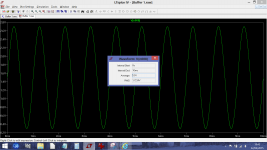
This shows something like you should see on either pin 5 or pin 8.
Notice how the notional centre line is biased to 1.5 volts. This allows the sine to swing up to +3 volts (your supply) and down toward zero.
So we have here a peak voltage of 1.2 volts and peak to peak of 2.4 volts. The rms value is Vpeak*square root of 2 so that becomes 1.2*1.414 which is 1.7 volts.
On your amp, because the speaker is driven by two antiphase signals it would see in this example 2.4 volts peak and so the rms value becomes 2.4*1.414 which is 3.4 volts. That would be a power of 1.4 watts rms into 8 ohm.
Attachments
- Status
- This old topic is closed. If you want to reopen this topic, contact a moderator using the "Report Post" button.
- Home
- Design & Build
- Parts
- Picking out parts for this schematic