Hi,
I think your are in your way in the programming.
I forget to mentioned you that you was right about the use of the OR gate in the shutdown If statement. It need an "OR" gate and not an "AND GATE".
It should be " if (float_int <= 29 || float_int >= 31) flag = 1;"
and not " if (float_int <= 29 && float_int >= 31) flag = 1; ". You need to change it in your program.
I'm testing and learning....
This string does not work, will not start up.
if (float_int <= 29 || float_int >= 31) flag = 1; // to value to use then is 29 and 31
I removed the = and it worked, apparently those two arguments conflict with the or statement
Should read like this.
if (float_int < 29 || float_int > 31) flag = 1; // to value to use then is 29 and 31
Question 2- Can I power down in reverse sequence without creating another variable?
Last edited:
Hi,
Are you referring to the shut down routine? I need more information on what you want to do. This routine what it does it is check the voltage limit and if they are out of limit it will call the power_off_seq to shut down the relays in reverse sequence from the start sequence.
Are you referring to the shut down routine? I need more information on what you want to do. This routine what it does it is check the voltage limit and if they are out of limit it will call the power_off_seq to shut down the relays in reverse sequence from the start sequence.
HI,
Just a suggestion as a troubleshoot tool make sure that the serial monitor it is ON after you started the program. The print command in line 90 will print you the filament voltage value in your PC monitor. It will let you know if the reading it is between 2.9 and 3.1 volt. Also by removing the = you are now checking for a limit of 28 and 32. It is possible that the reading from the filament was around 29 volt and the routine was turning off the amplifier due to a low voltage reading.
Just a suggestion as a troubleshoot tool make sure that the serial monitor it is ON after you started the program. The print command in line 90 will print you the filament voltage value in your PC monitor. It will let you know if the reading it is between 2.9 and 3.1 volt. Also by removing the = you are now checking for a limit of 28 and 32. It is possible that the reading from the filament was around 29 volt and the routine was turning off the amplifier due to a low voltage reading.
The routine was shutting off the amplifier if it was inside of the 2.9-3.1v using the = after the <> value.
Also the amplifier does not shut down in reverse, it starts with relay 1.
The delay time for 1,2,3 are set by the first delay value, the second and third delays have not effect on relay 2&3.
Attached file, this is the working version (except for the sequence and delay problem)
While monitoring the A0 input, the protection works perfect as-is. I can trim my calibration pot outside these ranges and the board shuts down as designed.
Edit:
Every once in a while the sequence wont start if the input voltage at A0 is not correct.
This voltage wont be stable until the last relay turns on
This loop shouldn't run until after the start up sequence
Attachments
Last edited:
Hi,
The testing was doing what it was supposed to do. If the voltage <= 2.9 it will shutdown. By changing to < 2.9 then it will shutdown if the voltage is less than 2.9 or need to be 2.8 to shutdown. The program was running OKAY but it is was done statically. Now we need to make some adjustment to run dynamically.
What about adding a delay in line 68 after the relay 3 it is enable? That will allow the system to stabilized before read the analog input. When you bypass the Varystor will make the voltage unstable since your are increasing the input voltage of the transformer. I will look into why it is not shutdown the relays in reverse order.
The amp is not live yet.
I am testing by using the 3.3v at Arduino and using a Pot to adjust the trigger.
I want to protect the amp after it starts by monitoring this voltage.
If it goes below 2.9 or above 3.1, I want the amp to trigger off.
I attached a version I better understand and it works but I have to do a software reboot (or power cycle) to restart the amp (which might not be a bad thing)
Attachments
Last edited:
I already connected all the LEDs to test the software which is how I found the problem. Its working good now with the last file I attached (bypassing the port string and turning each port on one at a time in sequence).
Thought I was doing that with the delay timers in the Atmel UNO? You might of missed the part of thread where I moved from PIC controller to AtmelWhy not using AVR's ? You can use the internal AVR timers & comparators. I did some programming for DMX decoding stuff. You can find many tutorials online and the IDE you can get free from Atmel and you can write in C or ASM.
Last edited:
Why not using AVR's ? You can use the internal AVR timers & comparators. I did some programming for DMX decoding stuff. You can find many tutorials online and the IDE you can get free from Atmel and you can write in C or ASM.
The Arduino uses an AVR. It uses an Atmega328.
I'm assuming the farh formula converts to fahrenheit?Hi,
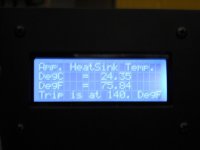
I used the LM35 to read the heat sink of my amplifier and shut down it if the temperature reached the set point. It is very accurate and simple to use. Your code for read the temp it is correct.
At this point I can use a if > to power off amp
At some point I think it would be cool to add a digital readout to display amp status during startup and also give readouts with a push of a button.
One could even calculate the power output and display it as well.
Read what Pete did on one of his amps, very cool stuff. The display will indicate the type of fault.
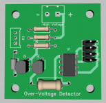
813 SE triode amps
Hi,
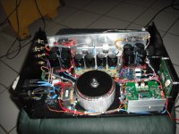
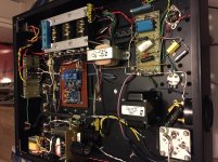
Attached are some pictures of my amplifier so you can have an idea what you can do with the micro and what do I do with the micro.
I control the following task of the amplifier:
1-Ramp the AC on power ON/OFF to prevent the inrush current.
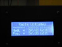
2-Ramp/control/regulate the rails voltages.
3-Monitor the heat sink temp and shutdown
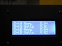
4-Display the watts/current/temperature
5-Monitor/shut the rails voltage to protect the speakers in case of high current.
Protect the speakers by shutting down the rails voltages. No SSR or
mechanical relays to protect the speakers..
6-Prevent the amplifier to power up itself in case of a power failure. It will
not restart when the power it is restore.
I did some cleaned up in the program shutdown subroutine. I added the temperature shutdown in the same line of the filament voltage shutdown. I will post it later that I have the time for you to check.
Attached are some pictures of my amplifier so you can have an idea what you can do with the micro and what do I do with the micro.
I control the following task of the amplifier:
1-Ramp the AC on power ON/OFF to prevent the inrush current.
2-Ramp/control/regulate the rails voltages.
3-Monitor the heat sink temp and shutdown
4-Display the watts/current/temperature
5-Monitor/shut the rails voltage to protect the speakers in case of high current.
Protect the speakers by shutting down the rails voltages. No SSR or
mechanical relays to protect the speakers..
6-Prevent the amplifier to power up itself in case of a power failure. It will
not restart when the power it is restore.
I did some cleaned up in the program shutdown subroutine. I added the temperature shutdown in the same line of the filament voltage shutdown. I will post it later that I have the time for you to check.
Attachments
Very nice, did you do this at one time or did it evolve like I'm doing?
Would like to see your code when I get some time. Right now I'm getting the basics done and need to make a few tweaks to the power supply. My "rail" voltage is running a little high at about 460volts (1200v at the high side of GM70). Need to adjust my cap input and drop it down to about 400v.
Eventually I need to clean up the control side and make a circuit board with all the components.
Attached a picture of my progress so far.
Attachments
Hi,
WoW that it is huge, nice layout and neat. My advice to you that the most important when designing the control board it is to make sure you have all the hardware needed and all the I/o needed. Also make sure that you have some extra spare I/O in the board just in case you missed something. Once you have the board made then all the changes will be done in the software.
I did it from the beginning but troubleshoot the programming to works right and without bugs took sometimes. Now, I am working to add a digital VU using the existing display.
Hi,
Attached it is the program file with some changes to the shutdown routine. Also I found the problem with the shutdown sequence. I was using increments "++" in the for/loop and should be decrements "--". Compare/check the changes with your last program. If you like the changes go ahead update them in your program or run the program to see if you like the changes to the program.
In the shutdown sequence you used delays turning off the relays. You do not suppose to shutdown the amplifier as soon as possible? Why the delays. Just a question.
Attachments
- Status
- This old topic is closed. If you want to reopen this topic, contact a moderator using the "Report Post" button.
- Home
- Design & Build
- Software Tools
- PIC programming