


12B4 Preamp


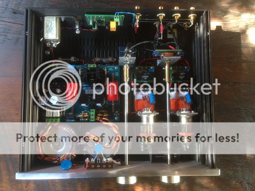

The preamp uses two New Old Stock (NOS) 12B4 tubes for a gain of 6.5 (16 dB). It has source selection (up to three inputs) and a volume control. Input impedance is 10K or 61K (depends on source selection, long story...) and an output impedance of ~500R.
The circuit is a common cathode gainstage with a Constant Current Source (CCS) plate load. The CCS combined with the choice of the 12B4 tube provides a very linear preamp (bias point is 100V @ 20mA). The power supply is regulated for both the high voltage supply (122V DC for both Left and Right B+) and the low voltage heater supply (12.6V DC).
I added a “555” relay timer circuit to mute the output of the preamp for 30 seconds upon start up, this circuit it powered off the 12.6V DC heater supply. This auxiliary circuit prevents a nasty pop sound upon start up that occurs when you have a solid state power supply and no standby switch.
I used low capacitance shielded wire for the signal runs, employed a star grounding scheme, used high quality toroidal transformers, used an over engineered very robust power supply and high quality components throughout, this created a preamp with very little floor noise.
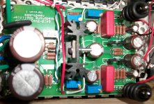
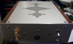
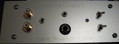
My newest headphone amp is pictured. It uses the 6418 subminiature directly heated pentode (wired as a triode) in a sort of hybrid mu-follower circuit that I devised using ZVN3306/ZVP3306 MOSFETs. A pair of D cell batteries supply the filament power. I designed the PCB using the ExpressPCB mini-board service, so have two spares. The tube is quite microphonic, but I have tried to minimize this issue with o-ring dampers and rubber washers on the PCB. Still, the sound is very nice: natural and very detailed. Quite an enjoyable little amp.
Attachments
Last edited:
The preamp uses two New Old Stock (NOS) 12B4 tubes for a gain of 6.5 (16 dB). It has source selection (up to three inputs) and a volume control. Input impedance is 10K or 61K (depends on source selection, long story...) and an output impedance of ~500R.
The circuit is a common cathode gainstage with a Constant Current Source (CCS) plate load. The CCS combined with the choice of the 12B4 tube provides a very linear preamp (bias point is 100V @ 20mA). The power supply is regulated for both the high voltage supply (122V DC for both Left and Right B+) and the low voltage heater supply (12.6V DC).
I added a “555” relay timer circuit to mute the output of the preamp for 30 seconds upon start up, this circuit it powered off the 12.6V DC heater supply. This auxiliary circuit prevents a nasty pop sound upon start up that occurs when you have a solid state power supply and no standby switch.
I used low capacitance shielded wire for the signal runs, employed a star grounding scheme, used high quality toroidal transformers, used an over engineered very robust power supply and high quality components throughout, this created a preamp with very little floor noise.
Hi Chris very nice compact build. Did you also find the bypass cap over the cathode resistor to have a huge influence on the sound? What capacitor did you use?
Regards
My newest headphone amp is pictured. It uses the 6418 subminiature directly heated pentode (wired as a triode) in a sort of hybrid mu-follower circuit that I devised using ZVN3306/ZVP3306 MOSFETs. A pair of D cell batteries supply the filament power. I designed the PCB using the ExpressPCB mini-board service, so have two spares. The tube is quite microphonic, but I have tried to minimize this issue with o-ring dampers and rubber washers on the PCB. Still, the sound is very nice: natural and very detailed. Quite an enjoyable little amp.
Schematic available ?
Schematic available ?
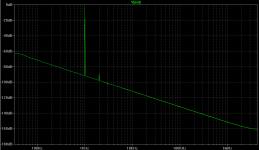
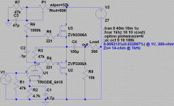
Sure; see attached. I just found out in the "hybrid output" thread that I have reinvented the wheel with this circuit: part of it first appeared in a 1958 patent. In my case, I stumbled upon the circuit by accident while trying to find a better way (other than a plain resistor) to get more current flowing through the mu-follower. It simulates with orders-of-magnitude better THD than the resistor-biased mu-follower, but I haven't measured it in real life due to lack of proper equipment. My ears judged it to be a fine performer, though.
There are likely small tweaks that could improve the circuit's sound and measured performance, but I built it as breadboarded for the first time out since that circuit sounded so nice. I am currently working on a modified version which uses a depletion FET for the mu-folower device, thus eliminating R6, R7, P1, C2, and C3.
Attachments
Last edited:
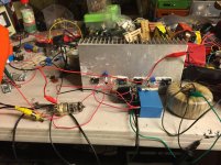
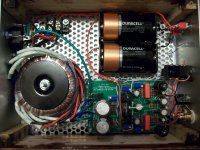
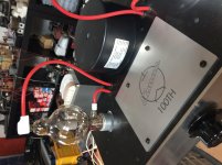
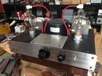
Eimac 100TH. 20W SET
700V B+
FET in depletion mode as pre. Gain of about 100x.
20W in 5 ohm
11 components per channel.
and a rather complex power supply
700V B+
FET in depletion mode as pre. Gain of about 100x.
20W in 5 ohm
11 components per channel.
and a rather complex power supply
Attachments

Last edited:
700V B+
FET in depletion mode as pre. Gain of about 100x.
20W in 5 ohm
11 components per channel.
and a rather complex power supply
I hope it sounds as great as it looks, this is a terrifying machine

Some sanity of a budget amp: 6n6p , sorry no inside picture yet. PPP :
An externally hosted image should be here but it was not working when we last tested it.
700V B+
FET in depletion mode as pre. Gain of about 100x.
20W in 5 ohm
11 components per channel.
and a rather complex power supply
everything great except pot knobs- Home
- Amplifiers
- Tubes / Valves
- Photo Gallery