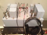
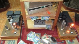
Sick as!Here an older pic of the current project, monoblocks with 813 in P-P. Driven by (Full Music) 300B, in turn driven by the respected 27. All (amorph.) iron from Tribute Audio.
Currently all brushed-anodized in black/silver, Xfrms in metallic dark red.
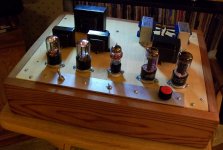
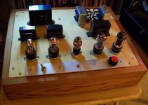
Here is my latest project.
It uses British valves all the way through, and puts out a whole three quarters of a watt.
Input valves (grey glass) are Osram MH4 triodes whilst the outputs are late 1930s Mazda Globe AC/P1
Sounds lovely.
A British Darling amplifier.
An externally hosted image should be here but it was not working when we last tested it.
It uses British valves all the way through, and puts out a whole three quarters of a watt.
Input valves (grey glass) are Osram MH4 triodes whilst the outputs are late 1930s Mazda Globe AC/P1
Sounds lovely.
A British Darling amplifier.
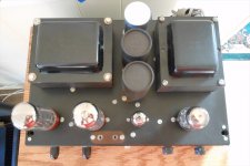
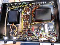
Here is the underside,
Very very simple, not a lot in there.
An externally hosted image should be here but it was not working when we last tested it.
Very very simple, not a lot in there.
Mate 3/4W you must be mad. But admire your GUTS!. I have just designed and prototyped a 1.2W SS amp but have not yet built it thinking it to "weak". Tell me how does your amp sound. I have Fostex FE206 back loaded horns (96db efficient) so your amp and mine should work well.
So how does it sound and in what speakers???????
So how does it sound and in what speakers???????
It sounds great actually.
Speakers are large 5ft Metronome quarter wave pipes with Fostex F225WK wide-range drivers plus horn tweeter helper. Efficiency is around 96dB/W.
Room size is 12ft x 13ft with a 9ft ceiling.
It throws a huge soundstage with plenty of micro dynamics and has a big, full-bodied presentation. I love it!
Speakers are large 5ft Metronome quarter wave pipes with Fostex F225WK wide-range drivers plus horn tweeter helper. Efficiency is around 96dB/W.
Room size is 12ft x 13ft with a 9ft ceiling.
It throws a huge soundstage with plenty of micro dynamics and has a big, full-bodied presentation. I love it!
1.5W
Hi there,
I've build plenty amps with 1 to 1.8 (max, max, max) output.
more then enough....
I never open them more then 3/4
Mate 3/4W you must be mad. But admire your GUTS!. I have just designed and prototyped a 1.2W SS amp but have not yet built it thinking it to "weak". Tell me how does your amp sound. I have Fostex FE206 back loaded horns (96db efficient) so your amp and mine should work well.
So how does it sound and in what speakers???????
Hi there,
I've build plenty amps with 1 to 1.8 (max, max, max) output.
more then enough....
I never open them more then 3/4
Here is my latest project.
An externally hosted image should be here but it was not working when we last tested it.
It uses British valves all the way through, and puts out a whole three quarters of a watt.
Input valves (grey glass) are Osram MH4 triodes whilst the outputs are late 1930s Mazda Globe AC/P1
Sounds lovely.
A British Darling amplifier.
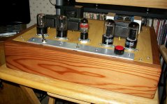
Its a green peace SE, conservationism to maximum expression.
They looks funny and beautiful. Good work.

Here is my latest project.
An externally hosted image should be here but it was not working when we last tested it.
It uses British valves all the way through, and puts out a whole three quarters of a watt.
Input valves (grey glass) are Osram MH4 triodes whilst the outputs are late 1930s Mazda Globe AC/P1
Sounds lovely.
A British Darling amplifier.
That's a nice one! Love the green color, fits perfectly with your wallpaper!
Guitar amp enclosure?
Knowing just enough to be dangerous = 1 glorious watt.
I thought I'd post some pics of my latest, almost complete, project. Basically after making a SSE tube amp this spring, I got the itch to try my hands at something else. I got some tube books, and read up on tube theory so I had some idea of how they work. I then got the idea to attempt to build a flea watt amp using cheap beam tubes and a voltage doubler for the power supply.
First I modeled a voltage doubler power supply using 25z6gt tubes in PSUD. Once I got a basic working power supply, I set about working up a amp, using a couple different designs as a guide, modeled in LTSpice. I chose the basic 6V6 as my guide tube and worked up a schematic on LTSpice, playing around tell I got parts values for a circuit that would put out a clean watt. I then chose the 12w6gt as my tube because their cheap. I got about 15 tubes for 2 bucks a piece.
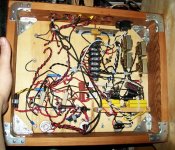
Still not sure if I knew what I was doing, I stated building, the amp figuring I'd either get smoke or sound. To my amazement I got sound and not smoke. Everything wasn't smooth sailing though as my "voltage doulber" was giving me 320 voltage under load making the output tubes to hot. I admit though I used silicon diodes in parallel with the rectifier tubes, so well the rectifier tubes are in the circuit, they are more for a light show. After putting a 50 ohm resister before the isolation transformer, I then got my voltage down enough so the output tubes won't burn out. The other small RAT Shack trannys are for the filaments. The output trannys are inexpensive EDCOR 5 watters spec'ed out for 40 to 18Khz.
The sound is very warm and smooth, just what I was aiming for when started this project, and though most of what I did was old hat for many here, for me it was quite new and must admit I'm pleased with myself. Any way here are the Pics, and yes I admit the wiring is helter skelter, but there was a method to my madness and the amp is dead quiet.
I thought I'd post some pics of my latest, almost complete, project. Basically after making a SSE tube amp this spring, I got the itch to try my hands at something else. I got some tube books, and read up on tube theory so I had some idea of how they work. I then got the idea to attempt to build a flea watt amp using cheap beam tubes and a voltage doubler for the power supply.
First I modeled a voltage doubler power supply using 25z6gt tubes in PSUD. Once I got a basic working power supply, I set about working up a amp, using a couple different designs as a guide, modeled in LTSpice. I chose the basic 6V6 as my guide tube and worked up a schematic on LTSpice, playing around tell I got parts values for a circuit that would put out a clean watt. I then chose the 12w6gt as my tube because their cheap. I got about 15 tubes for 2 bucks a piece.
Still not sure if I knew what I was doing, I stated building, the amp figuring I'd either get smoke or sound. To my amazement I got sound and not smoke. Everything wasn't smooth sailing though as my "voltage doulber" was giving me 320 voltage under load making the output tubes to hot. I admit though I used silicon diodes in parallel with the rectifier tubes, so well the rectifier tubes are in the circuit, they are more for a light show. After putting a 50 ohm resister before the isolation transformer, I then got my voltage down enough so the output tubes won't burn out. The other small RAT Shack trannys are for the filaments. The output trannys are inexpensive EDCOR 5 watters spec'ed out for 40 to 18Khz.
The sound is very warm and smooth, just what I was aiming for when started this project, and though most of what I did was old hat for many here, for me it was quite new and must admit I'm pleased with myself. Any way here are the Pics, and yes I admit the wiring is helter skelter, but there was a method to my madness and the amp is dead quiet.
Attachments
My circa 1960 Heathkit AA-81. Aww, idn't it cute? It's in near time capsule condition. Do you see any dangerously old components in the circuit? Maybe I should have the older caps changed out?
Attachments
looks in wonderful condition. ... best to get rid of the old caps, can destroy your EL34's. they may be ok, but not worth the risk
Phil
Yes, that would have been my suggestion as well. Capacitors of that vintage can be a serious problem. Modern capacitors might also improve the sound quality and "hum bucking", especially in the power supply/power filtering circuit. (It is possible to keep the topside paper cans in place for appearances sake, the three big guys on top, and "gut the cans" or install alternates inside the chassis.)
As for other sound quality improvements, you might consider replacing any carbon resistors and/or wire wound resistors directly in the audio signal path with like versions of metal film resistors (or other, less noisy types).
I'm more transistor oriented, so others here in the tube section would probably have better advise.
That Heath Kit really is a treasure ... keep the faith
Last edited:
If you are in the mood to tinker with such a cool toy, I agree with the suggestion to replace the capacitors. Start with the smaller ones, then do the 'can' caps. (Replacements for those will be harder to source)
You might want to consider leaving the 'can' caps in place (for aesthetics), but disconnected, and mount a number of modern caps under the chassis.
Leave the resistors unless any have drifted way off spec.
You might want to consider leaving the 'can' caps in place (for aesthetics), but disconnected, and mount a number of modern caps under the chassis.
Leave the resistors unless any have drifted way off spec.
Here is my latest project.
An externally hosted image should be here but it was not working when we last tested it.
Very stylish!
Simply, but tastefully!
Good for you!
I thought the resistors were usually OK as long as they don't look cooked and test OK. I have the build manual for the AA-121, which was the stereo version, so I will have a chart to use when checking values and paths. Thanks everyone for the tips. I'll get the caps changed out before putting many hours on it.
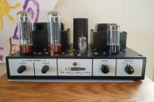
Thought you guys might find this interesting. Just finished restoring this. Everything is original, I personally like the Allen Bradley carbon resistors the best, though instead of the wax and paper caps I'm using vintage brown Cornell Dubiliers. It is a McCurdy AM-405 amplifier that uses input transformers. Currently I'm using it as a headphone amp and a speaker amp, puts out about 5 watts but it has got to be the best el84 amp I've heard to date, dead silent due to the input transformers. Amplifier is from around 1948 and was used in Canadian radio stations, sounds a lot like Western Electric gear. I'll try to take some internal pics if you're interested. (just in case you're wondering my preamp inverts phase)
Attachments
- Home
- Amplifiers
- Tubes / Valves
- Photo Gallery