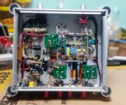
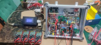
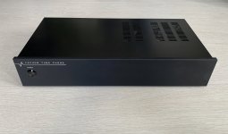
Yes you right , it's preamp/tone control . BT problem not solved, I need a small preamp , may be a dual OP amp.Is the last unit a preamp / tone control?
We discussed blue tooth modules recently- did you get that issue resolved? ( I see the BT antenna).
All look commercially produced, alex- very nice.
Jim
alex,
It seems we were discussing the M18 BT module. Have you tried accessing the internal volume control by using the 'Key' pin?
https://www.aliexpress.com/item/3256801450241749.html?spm=a2g0o.productlist.0.0.50b6442eEyWBa5&algo_pvid=a4cf8eac-9f33-4aab-bb41-378fb11ae106&algo_exp_id=a4cf8eac-9f33-4aab-bb41-378fb11ae106-0&pdp_ext_f={"sku_id":"12000016918379833"}&pdp_npi=2@dis!USD!!0.88!!!!!@2101fd4b16544363961551011eb609!12000016918379833!sea
The circuit shown in link uses 2 resistors for vol+ / vol-. Simple enough to try, since you already have it applied.
Jim
I'll try, you give me a nice solution .alex,
It seems we were discussing the M18 BT module. Have you tried accessing the internal volume control by using the 'Key' pin?
https://www.aliexpress.com/item/3256801450241749.html?spm=a2g0o.productlist.0.0.50b6442eEyWBa5&algo_pvid=a4cf8eac-9f33-4aab-bb41-378fb11ae106&algo_exp_id=a4cf8eac-9f33-4aab-bb41-378fb11ae106-0&pdp_ext_f={"sku_id":"12000016918379833"}&pdp_npi=2@dis!USD!!0.88!!!!!@2101fd4b16544363961551011eb609!12000016918379833!sea
The circuit shown in link uses 2 resistors for vol+ / vol-. Simple enough to try, since you already have it applied.
Jim
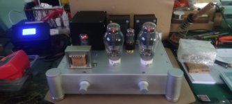
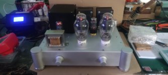
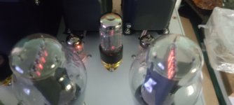
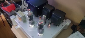
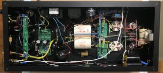
300b SET, 7DJ8 cascode, 6SN7 cathode followers......sounds fabulous....
Attachments
-
 IMG_20220422_123418.jpg464.3 KB · Views: 471
 -
 IMG_20220517_084945.jpg278.5 KB · Views: 370
 -
 IMG_20220520_091759.jpg163.3 KB · Views: 353
 -
 IMG_20220520_091801.jpg178.1 KB · Views: 351
 -
 IMG_20220520_091808.jpg151.5 KB · Views: 313
 -
 IMG_20220520_091814.jpg155 KB · Views: 310
 -
 IMG_20220520_091917.jpg159.5 KB · Views: 435
 -
 IMG_20220520_092459.jpg151.3 KB · Views: 484
Great looking build, and I wish there were more builds using see-through constructions.
These 4 300B PSE amps were built about 10 years ago. The owner hadn't been able to listen to them for 2 years because of serious hum problems in 2 of them.
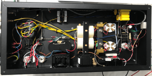
When I opened them up it was apparent the builder had tried unsuccessfully to implement an earth bus. Two of the amps had the mains earth connected to the negative speaker terminal which was actually insulated from the chassis. The workmanship was appalling with terrible soldering (lots of dry joints), earth loops, 10W resistors glued directly to the chassis and large filter capacitors glued to the chassis on rafts of pop sticks. The 25W 300B cathode resistors were not attached to the chassis at all and one was open circuit.
It was surprising that the owner had been able to enjoy listening to the amps at all!
The 2 major hum problems were easily fixed but the noise level in all 4 amps was poor and plainly audible. The owner thought that was par for the course with valve amps.
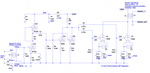
Completely re-working the earth buses, additional power supply capacitors, rectifying, filtering and regulating the ECC82 and 6H8C heaters (could probably just have fixed the heater wiring and done without that), and Coleman filament regulators reduced the noise level by 6-7dB to barely audible with your ear next to the speaker driver.
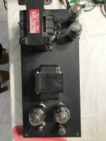
The amps now sound great but I have to say that they get really warm after they’ve been on for a few hours. Even the mains transformers are warm. I just measured the chassis top at 33°C and inside one of the air holes at 38°C. And that’s after I improved the air-flow by drilling large holes in the bottom plate and a couple of large holes in the top plate partially obscured by the output transformers. The owner said he hardly listens to them during the summer!
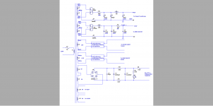
I’ve not worked with 300B SE amps before and I’ve learned a lot. Probably the main thing I’ve learned is never to assume the original builder/designer knew what they were doing. It took me way longer than it should to realise that there was insufficient power supply filtering (the filter caps are physically huge but only 47uF).
Just recently, after trying different 300Bs and noting 3x distortion with some and wondering why, I realized that the HT is too high at 450V (I measured 467V one day). Solution would be a voltage regulator in each of them to drop the HT down to 420V or a bit less.
Still, the owner has very efficient full-range drivers and listened to the amps happily enough for a few years at the current 300B operating point. I’ve also had enough of drilling and tapping the 10mm thick top plate (probably why the original builder glued all the filter caps to the chassis!).
If I were designing these amps from scratch there wouldn’t be a separate power supply for the input and driver stages. That would eliminate a rectifier and it’s 3A heater requirement. I’d also go for fixed bias of the 300Bs with bias servos. That would eliminate another source of heat in the cathode resistors. With the mains here specified at 230V ±10% (I’ve seen 220V at night and 247V when everyone’s solar is running) I put voltage regulators in all my amps. The chassis would also be much better ventilated.
I’ve built up a lot of muscles carrying these amps between my workbench, my study for testing and the HiFi rack over the last 3 months. I won’t miss that!
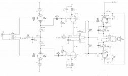
I’ve attached before and after pictures, top view, schematics and measurements.
Attachments
-
 IMG_3036-1.png476.7 KB · Views: 294
 -
 IMG_3191.JPEG363.5 KB · Views: 291
 -
 IMG_3035.JPEG394.4 KB · Views: 369
 -
 Modified Amp Schematic.png48.1 KB · Views: 371
 -
 Modified Power Supply Schematic.png33.5 KB · Views: 346
 -
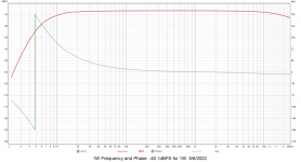 1W frequency and phase.png53.9 KB · Views: 260
 -
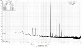 1W 1kHz THD+N.png55.5 KB · Views: 216
 -
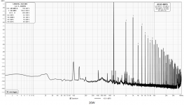 20W 1kHz THD+N.png66.3 KB · Views: 222
Nice work!The amps now sound great but I have to say that they get really warm after they’ve been on for a few hours. Even the mains transformers are warm. I just measured the chassis top at 33°C and inside one of the air holes at 38°C. And that’s after I improved the air-flow by drilling large holes in the bottom plate and a couple of large holes in the top plate partially obscured by the output transformers. The owner said he hardly listens to them during the summer!
33°C and 38°C are "really warm" to you? LMAO My body temperature is 37°C
 Seriously though, I have transformers that run hotter than that with no load - just plugged into the wall waiting for a purpose.
My chassis temperature is up to 75°C usually, but I have one Hammond that runs at 95°C (It's within spec - apparently they just run hot).
I don't swiss cheese my chassis - there is a small ring gap around the tubes - that's it.
I also run long life 105°C rated caps because I design them to run that hot
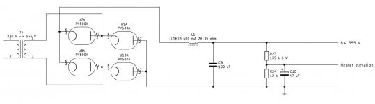
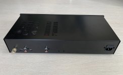
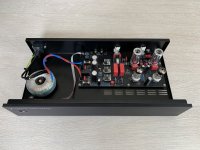
My new cathode follower push-pull mono blocks:


Outputs a bit over 20 W each in class A. The output tubes are triode connected PL519. First stage tube is ECC85 and second stage tubes are 6S4A. Rectifiers are PY500A connected as a bridge. Sounds great and will keep the living room nice and warm.
Outputs a bit over 20 W each in class A. The output tubes are triode connected PL519. First stage tube is ECC85 and second stage tubes are 6S4A. Rectifiers are PY500A connected as a bridge. Sounds great and will keep the living room nice and warm.
Attachments
Thanks! I think the Tektronix transformers are quite cool.Cool build and nice use of TEK iron! where did you get those tube cages?
I bought the tube cages here: http://www.fragjanzuerst.de/eindex.htm?/ekatalog.htm Product number PASS0019.
Finally, I have an Ikea rack, with amplifiers on lamps built by me. I'm listening, from the Onkyo C-N7050 network player, via SMSL SU-9, Taga Harmony Platinum F-120 speakers, amplifiers on PP tubes with EL 84, EL34, 6P3C, and KT88. I do not use tonal corrections, no IMHO is required. Next, the acoustic treatment of the camera, the audition. I declare myself satisfied with the achievements. 😘🤗
Regards,
Alex mm


Regards,
Alex mm
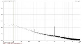
Hey, this is my first passive RIAA phono preamp. Much better sounding than all active ones I've built... no feedback and thd ~0,016%!!
Input is ECC83 SRPP -> passive riaa -> ECC83 DC coupled to ECC82 follower. All regulated PSUs, 555 on/off switch + remote on, 4060 turn-on mute delay.

more images below...
Input is ECC83 SRPP -> passive riaa -> ECC83 DC coupled to ECC82 follower. All regulated PSUs, 555 on/off switch + remote on, 4060 turn-on mute delay.
more images below...
Attachments
- Home
- Amplifiers
- Tubes / Valves
- Photo Gallery