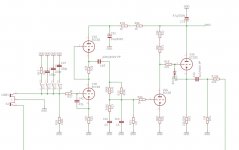
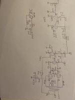
First stage is 0,73V = 1,5mA
Second stage is 0,8V = 1mA
Follower is 140V = 6.5-7mA
Pretty much corresponds to simulations and tube tolerances. However voltages are a bit off that whats in schematic, due to resistor tolerances in regulator I am having +310V PSU and so first stage is around 306V
Btw I noticed a bit lowered low frequencies when used with low output impedances. Right now I have 1uF and its ok for 47k load, however with 10k load it has like -3dB on 20Hz which is not good, so its better to use bigger output cap to be more versatile, I am going to change mine to 6u or so...

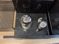
Where did you get these DMM's? Many thanks, Erik
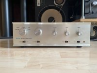
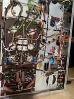
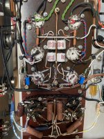
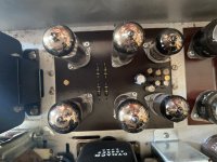
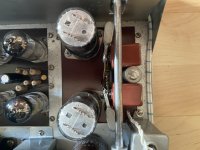
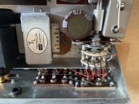
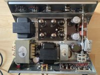
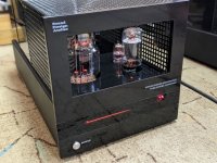
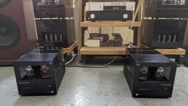
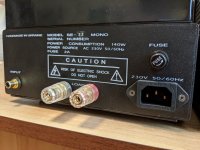
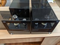
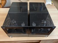
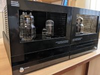
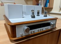
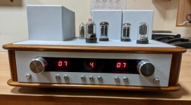
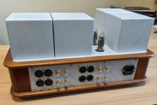
After almost a year of planing and building and tens of hours of listening and small corrections and adjustments, I am finally done with this little gem. The basis is a lovely integrated, model Dynaco SCA 35. Apart from this, I only kept the chassis and output transformers. I changed the power transformer and added a choke (made custom and cheap at Thermionic Lab). I designed a simple preamplifier around 12SX7 which is driven by a piher volume pot and multi position military type switch moved to the back of the chassis. The amp is a simple ultralinear design, driven by a Mullard E88CC in cathodyne phase inverter with 8dB of global feedback taken from the 8Ω secondary. Output tubes are Amperex Holland at the moment and ready to try Sylvania 6BQ5, Philips and Russia equivalents. It can also now be used as separate preamplifier and final amplifier. The sound is very different from the original and suits my music taste better. It is now able to drive even my L100s, not to mention how nice it mates with my Tannoys.
Not that it really matters, but it is easily the most clear and powerful amp at 15w I have ever heard and I have heard a lot…
Not that it really matters, but it is easily the most clear and powerful amp at 15w I have ever heard and I have heard a lot…
Attachments
-
 196CAF8E-5919-4CFA-85BC-73EA503141EF.jpeg348.2 KB · Views: 336
 -
 9354FC85-1EEF-47F9-B1B7-90AADAC2E064.jpeg699.2 KB · Views: 339
 -
 46E18B7E-2F93-4DF3-8B90-82034B7B2A35.jpeg666.7 KB · Views: 326
 -
 F239D884-C6BA-44C6-BA15-D749F02F243D.jpeg438.1 KB · Views: 306
 -
 EBC5F1F9-229E-4B19-AD48-38426E2AC0E7.jpeg438 KB · Views: 303
 -
 129CB3BC-802F-4595-B3A9-63A163C1A74F.jpeg500.3 KB · Views: 306
 -
 C0FCA501-EF69-465A-A369-CE20651C33C5.jpeg577.7 KB · Views: 326
I do not really have a schematic as such, but I will try to paint something since there is interest.Panos very interesting amp and glad sound so good, if you want and like why not share the schematic? ...all the best
Very well spotted! I am posting the corrected schematicanode first to grid of second 6SN7 triode
Attachments
I'm working on a low gain line stage (4x gain). This is the second PCB layout I've had made by JLCPCB. I made some mistakes in sizing components, but I'm learning. I should have made the pads bigger and put in some ventilation holes too. Next one should be better.


Last edited:
Thanks! I'm working on a more ambitious PCB to replace the PCB in an old, gutted Dyna Stereo 70 amp. I haven't sent the gerbers to JLCPCB yet because I'm afraid I may have overlooked or forgotten something. I need to go back with fresh eyes and give it a good going over. It will be a 6EJ7 pentode LTP to drive push-pull 6L6s in UL, with 'E-linear' feedback from the 6L6 screens to grids. And of course I need to finish this project first...
Analog Ethos 2A3 SET kit Legendarium

Re-capped with Duelunds:

Very nice kit, easy to assemble and it sounds great!
Re-capped with Duelunds:
Very nice kit, easy to assemble and it sounds great!

Member
Joined 2009
Paid Member
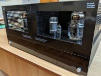
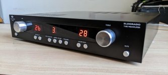
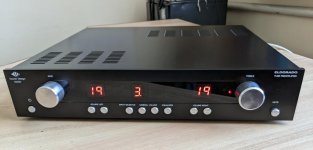
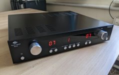
Looks very nice!Hey, this is my first passive RIAA phono preamp. Much better sounding than all active ones I've built... no feedback and thd ~0,016%!!
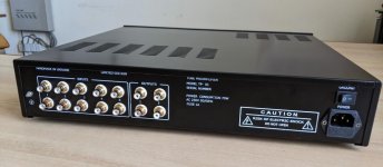
Input is ECC83 SRPP -> passive riaa -> ECC83 DC coupled to ECC82 follower. All regulated PSUs, 555 on/off switch + remote on, 4060 turn-on mute delay.
View attachment 1075555
more images below...
Did you find the output relay was really needed - as in, do you know if the design produces turn on and turn off 'plops'? I'm wondering if I need to do the same thing with my preamp project, but it has a tube rectifier so slow warm up.
I love the blue glow, Dave.
- Home
- Amplifiers
- Tubes / Valves
- Photo Gallery