Thanks for the private heads up!!!
I can feel it, somebody's watching us...
Many thanks Ian, and no shame gathering info and use, the info is here already and no need to re-invent the wheel. The only fair thing is to share it for lost souls, as you did. Great!
Matthieu
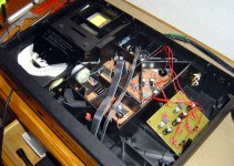
If anyone is interested while we're on clocking, here's the link to the post the day I fitted the awesome C2.
http://www.diyaudio.com/forums/digital-source/133780-philips-cd650-mods-73.html#post1851461
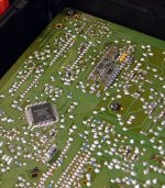
Been some changes since the photo too. All the regs on the TDA are SPower + some silvered mica in the HF area.
Also, today I hooked up my green DAC and Meridian via the main system. It is very good but then its already using a lot of what I've learned on this thread and others. However, it is apparent that the use of intermediate upgrade parts will not yeald the gains I have experienced in the CD960!
12 months ago, i'd have been over the moon with the dac, but the 960 is so so much better!
http://www.diyaudio.com/forums/digital-source/133780-philips-cd650-mods-73.html#post1851461
Been some changes since the photo too. All the regs on the TDA are SPower + some silvered mica in the HF area.
Also, today I hooked up my green DAC and Meridian via the main system. It is very good but then its already using a lot of what I've learned on this thread and others. However, it is apparent that the use of intermediate upgrade parts will not yeald the gains I have experienced in the CD960!
12 months ago, i'd have been over the moon with the dac, but the 960 is so so much better!
Bit Decouple theory!
Hi guys,
I'm working on a PCB that has the TDA, regs and output stage to put inside my latest project!
I'm currently looking at the "bit" decoupling.
Currently I use 1uF MKP's on msb and 220nF on the the others.
I've read the theory in the Ultimate NOS thread about the changing values due to timing of current throught the gates inside the chip itself and will try the suggested values in this latest implementation.
My problem is this:-
The traces are too long (imho)from the DAC to the cap due to the size of the components selected (MKP).
Any thoughts on using PPS connected straight to the pins of the DAC insread? Also is would tant be any good here?
If MKP are very good here (they sound good to me in the current set up) could pps bypass on the chip pins work in addition to the mkps?
What should be considered when deciding which type on cap construction to go for
Last edited:
I'll use them, and one for the DEM pins.
You should run a DEM reclock here Matthieu. It a very worthwhile mod.
I can feel it, somebody's watching us...
Matthieu
You mean other than the spooks at Echelon?
Hi there,
as I see you'll fit your output stage, can you insert it between the TDA and the onboard output caps and still leave the opamp output powered (but the TDA channels in)?
I mean on the player there are things like Kill and DEMM related to output stage and ICs. I wonder as my output stage does only white noise while playing (and slience when stop, quite normal with the kill on).
Matthieu
Not fully // Ian,
the TDA's pins only connected to one OS, then to the output caps. (wich are on the PCB...) All is still powered... and I just mind that my external PSU is feeding my OS with no ground to the player (+/GND to OS, that's all, no GND from OS to player).
I've built this one : http://www.lampizator.eu/LAMPIZATOR/FETISHIZATOR/JFET_CDout.pdf maybe a mistake here but it's so simple (more than the CD63 DOS!) I don't think so.
I'm still not fully sure I understand what you are asking Matthieu.
If it was me, i'd remove the opamps from the pcb if they are not in use. I'd also remove anything on the board not used if its going to be attached to the signal path. I'd also link the gnd's together. If you have floating gnd's you'll have all sorts of problems. It will at best hum!
I'd expect that circuit to be ace too!
Have you got a decent reg on the filter chip yet? I'd say its the biggest single gain you'll make (but it must be a low noise reg, LM317 won't give you the gains you need here).
Ian
Yes guys,
I was just trying the output before fitting it without removing the factory's one and using an external PSU. No way, only real settings work. BB's ICs are gone as their caps, output burnin' in time...
No more white noise but music!
Thanks for support,
Matthieu
I was just trying the output before fitting it without removing the factory's one and using an external PSU. No way, only real settings work. BB's ICs are gone as their caps, output burnin' in time...
No more white noise but music!
Thanks for support,
Matthieu
Attachments
- Home
- Source & Line
- Digital Source
- Philips CD650 mods