Re: CD104 = B & O CDX
Hi I've got a Marantz CD63 old version and I read from somewhere that the internal is quite similar to the Philips 104. My player refuses to read a disc. When you hit play, it start spinning the disc and it gets faster and then slow down and stop then nothing happen. You can see that the laser head is moving up and down trying to do something but nothing coming out of it. Have you got any idea what is the problem? Would really like to get it back to work. Also if you could email me a copy of the schematic you have on the CDX that will be really helpful. Thanks in advance. my email address:
hjackxiao@yahoo.com.au
jives11 said:greetings,
Don't have CD104 schematics but do have B&O CDX which internally is almost the same. Schematics should be in your inbox as you read this.
Hi I've got a Marantz CD63 old version and I read from somewhere that the internal is quite similar to the Philips 104. My player refuses to read a disc. When you hit play, it start spinning the disc and it gets faster and then slow down and stop then nothing happen. You can see that the laser head is moving up and down trying to do something but nothing coming out of it. Have you got any idea what is the problem? Would really like to get it back to work. Also if you could email me a copy of the schematic you have on the CDX that will be really helpful. Thanks in advance. my email address:
hjackxiao@yahoo.com.au
Re: Re: CD104 = B & O CDX
I'll happily email you a CD104 schematic BUT the CD63 was based on the earlier Philips CD101. The CD63/101 were top loaders. the marantz version of the CD104 was called the CD34. to add to the confusion the B&O version of the CD104 is the CDX, but B&O re-engineered it as a toploader , even though the 104/CD34 implementation is a drawer loader.
There are good threads on the CD101 here, but the classic fix to 90% of CD104 problems (replacing the griplets) is unnecessary on the CD101. I think the PSU caps are the first starting point , maybe check the regulators too, but lets confirm first which you have.
PS You'll need an Inbox capable of accepting a 12Mb attachment ( your listed one bounces - too big). googlemail can do it and is quite easy to register, even as a one time mail drop
jackx said:
Hi I've got a Marantz CD63 old version and I read from somewhere that the internal is quite similar to the Philips 104. My player refuses to read a disc. When you hit play, it start spinning the disc and it gets faster and then slow down and stop then nothing happen. You can see that the laser head is moving up and down trying to do something but nothing coming out of it. Have you got any idea what is the problem? Would really like to get it back to work. Also if you could email me a copy of the schematic you have on the CDX that will be really helpful. Thanks in advance. my email address:
hjackxiao@yahoo.com.au
I'll happily email you a CD104 schematic BUT the CD63 was based on the earlier Philips CD101. The CD63/101 were top loaders. the marantz version of the CD104 was called the CD34. to add to the confusion the B&O version of the CD104 is the CDX, but B&O re-engineered it as a toploader , even though the 104/CD34 implementation is a drawer loader.
There are good threads on the CD101 here, but the classic fix to 90% of CD104 problems (replacing the griplets) is unnecessary on the CD101. I think the PSU caps are the first starting point , maybe check the regulators too, but lets confirm first which you have.
PS You'll need an Inbox capable of accepting a 12Mb attachment ( your listed one bounces - too big). googlemail can do it and is quite easy to register, even as a one time mail drop
wojtek.l said:Hi,
Is it possible know the value of resistors on out rca ground to ground of chassy on cd7550 grundig?
It is only resistors on board rca out.
Thanks
Yes, it is capicitor 2n2.
Hi,
Are you sure that a capacitor?
It sounds like a normal resistors with these colors:
Red red red gold silver
But I did not understand the value,
With the tester does not measure
wojtek.l said:Yes, this is capicitor. I know this solution. You can try 2n2 -10 nF also. Please to look at another Grundig equipment like v7000, v1700, v35 (also similar solution). This is only a part of advanced ground technology in the best product of Grundig.
is it possible to post a circuit diagram of how this looks ?
Sbrindolone said:
Hi,
Are you sure that a capacitor?
It sounds like a normal resistors with these colors:
Red red red gold silver
But I did not understand the value,
With the tester does not measure
Hi
wojtek.l is correct, its a capacitor.
They look like resistors and the color band have the same meaning.
In your case :
Red - 2
Red - 2
Red - 2 zeros
Gold- tolerance.
That give 2.200 pF or 2,2 nF as wojtek.l have already told you.
If you still have doubts, inspect with a capacitance meter...
")
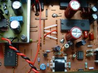
Is like this ( the one in the upper right corner )...
Attachments
You reason is a capacitor.
You know more information about this special grundig ground?
If you do not know if, in italy many people talk about certain products grundig, saying that playing in a special way.
I repeat not all just a dozen products of a well-specified period.
You know more information about this special grundig ground?
If you do not know if, in italy many people talk about certain products grundig, saying that playing in a special way.
I repeat not all just a dozen products of a well-specified period.
Sbrindolone said:This is only a part of advanced ground technology in the best product of Grundig.
Quote
I'm sure you're right, but I still challenge anyone to detail what this mythical Grundig earthing arrangement is. I would buy a Grundig 7550 if my CD104 broke as I like the simple style of it, so I don't doubt it is a good player. I'd just like to see a picture or schematic which supports this view. I cannot see anything here which isn't 100% Philips but maybe the changes are hidden beneath the board or on the chasis end of the connectors ?
http://www.dcaudio.kgb.pl/grundig7550.htm
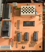
petronius said:Please help I have Philips CD 304 it similar like 104 and I am put in non os follow this picture now I have very distort sound did I miss something or what please help
Thanks
Did you put the SAA 7000 in the 14 bit output mode by
putting pin 16 high ?
original in the 104 ( 304) the saa 7000 outputs in 16 bit mode.
You have to put the SAA7000 in 14 bit mode by disconnect pin 16 from ground and connect it to + 5 volt through a resistor of 1k
(FI to pin 18 = +5v)
The removed SAA 7020 takes 16 bit but outputs 14 bit and the TDA 1540p takes only 14 bit !!
Succes
Onno
Hallo,wojtek.l said:Yes, this is capicitor. I know this solution. You can try 2n2 -10 nF also. Please to look at another Grundig equipment like v7000, v1700, v35 (also similar solution). This is only a part of advanced ground technology in the best product of Grundig.
could you please explain better how the "hf grounding" works.
Thanks.
Max
- Home
- Source & Line
- Digital Source
- Philips CD104 tweaks