My Grundig CD7550 has developed a mechanical problem with the cd drawer so I'll be pulling it apart this weekend.
I promised a while back I'd take some pics the next time I pulled it apart and post them. If anyone wants me to look at anything in particular then shout and I'll try and provide some feedback.
I promised a while back I'd take some pics the next time I pulled it apart and post them. If anyone wants me to look at anything in particular then shout and I'll try and provide some feedback.
I'd like to join IAN01. I can provide you guys with detailed pictures of my CD7550.
I already made some improvements to it. Put some high quality opamps like: LM4562 and removed the old electrolytics. Opamp's output goes trough 1uF propylene WIMA cap in parallel with 100uF Nichicon Muse. 100k load resistor at the end. No other unwanted parts. Removing the 100uF cap leads to higher rollback at low frequencies. From what I hear I could say this opamp sounds lovely and far more detailed than 5532. This feature combined with the warm and smooth sound of 1540 gives stunning results.
I already made some improvements to it. Put some high quality opamps like: LM4562 and removed the old electrolytics. Opamp's output goes trough 1uF propylene WIMA cap in parallel with 100uF Nichicon Muse. 100k load resistor at the end. No other unwanted parts. Removing the 100uF cap leads to higher rollback at low frequencies. From what I hear I could say this opamp sounds lovely and far more detailed than 5532. This feature combined with the warm and smooth sound of 1540 gives stunning results.
I think that RCA PCB might be where the earthing changes occur as the only pictures I've seen show standard Philips boards for servo and decoders.
Is it possible that those resistors are actually something else - I have seen small pink axial resistors which were in fact capacitors, and small inductors can look like high value carbon resistors.
or maybe it's the Grundig magic smoke , which if you're not careful you will allow to escape from the unit
Lets not forget, that this is a commercial product. So the Grundig brand needed a little advertising in order to make people buy their product. This product has been developed for the young High end market. As you know the High-end market is a bit surrounded with mystique I have both CD304 mkI and CD7550. I made comparison between these two models and they sounded pretty much the same to me. Grundig CD7550 looks way batter though Especially the silver version which sits on top of my audio rack The lack of remote control is of no concern to me
I have both CD304 mkI and CD7550. I made comparison between these two models and they sounded pretty much the same to me. Grundig CD7550 looks way batter though Especially the silver version which sits on top of my audio rack The lack of remote control is of no concern to me Hi Simonov,
I think you are absolutely right. I think it probably comes down to design. I like the simple style of the 7550. My CD104 is a little "busy" in the design and ergonomics and some later 104's had lots of transfers in different colours and typefaces which is a bit too much. However the B&O CDX would beat both IMHO
I think you are absolutely right. I think it probably comes down to design. I like the simple style of the 7550. My CD104 is a little "busy" in the design and ergonomics and some later 104's had lots of transfers in different colours and typefaces which is a bit too much. However the B&O CDX would beat both IMHO
GRUNDIG CD7550
Successfully repaired the unit this afternoon. I will take some close up photos tomorrow as the light is getting a bit low at the moment.
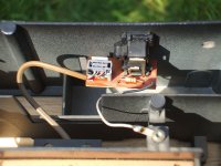
I can however confirm that the output Phono Assembly has a 2.2nF capacitor from the signal earth to the die cast chassis despite it looking like a resistor, as I took it out and measured it.
Successfully repaired the unit this afternoon. I will take some close up photos tomorrow as the light is getting a bit low at the moment.
I can however confirm that the output Phono Assembly has a 2.2nF capacitor from the signal earth to the die cast chassis despite it looking like a resistor, as I took it out and measured it.
That would imply that the decoder and servo boards ground is insulated from the chassis ? I think on the CD104 the boards are earthed via the connecting screws to the copper layer on both sides of the board. I wonder how easy it would be to retro-fit the Grundig earthing arrangement to a regular 104 ?
That would make sense as the decoder and servo boards are held within a plastic assembly suspended in the centre of a larger chamber in the die cast chassis.
I have put the unit away for tonight but I'll check that in more detail tomorrow and confirm your deductions on the earthing arrangements.
I have put the unit away for tonight but I'll check that in more detail tomorrow and confirm your deductions on the earthing arrangements.
That’s got me thinking now ... I also have a Grundig V1700 amplifier which is also rumoured to have the same special earthing arrangements ... it certainly is a beautiful sounding amplifier. Think I might pull that apart and see if it has the same arrangement as the CD7550.
I know the Italians who rave about the Grundig’s talk about CCI technology (Circuit Chassis Interface). So maybe this is all starting to fall into place now. The chassis is isolated DC wise but closely coupled at high frequency. Quite why that makes a difference I'm not immediately sure!
I know the Italians who rave about the Grundig’s talk about CCI technology (Circuit Chassis Interface). So maybe this is all starting to fall into place now. The chassis is isolated DC wise but closely coupled at high frequency. Quite why that makes a difference I'm not immediately sure!
jives11 said:I think on the CD104 the boards are earthed via the connecting screws to the copper layer on both sides of the board. I
This is simply not true ! (perhaps yes for your thinking
Philips is not stupid !
Regards
Onno
Onnosr said:jives11 said:I think on the CD104 the boards are earthed via the connecting screws to the copper layer on both sides of the board. I
This is simply not true ! (perhaps yes for your thinking
Philips is not stupid !
Regards
Onno
OK - sorry , like I said I was working from memory. So where does the philips connect to ground ? I guess just linking the signal ground to the case via a 2.2nf cap is not enough ?
Here is the pic of the Phono Assembly on the CD7550. Note the grey wire leading from the 2.2nF Cap on the board to the chassis pillar in the foreground.
Interestingly, the chassis is connected to the circuit earth via the Power Supply Board.
Interestingly, the chassis is connected to the circuit earth via the Power Supply Board.
Attachments
- Home
- Source & Line
- Digital Source
- Philips CD104 tweaks