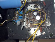
Today i have tried a CD player... a DVD player playing MP3
I have abandoned my Philips Class D because the internal oscilation produces a dirty ground... you feel the 500 Kilohertz into the ground.
Also i have abandoned the MP3 player.... hard to operate... smaller than my fingers... boring to operate.
Here is today picture.
regards,
Carlos
I have abandoned my Philips Class D because the internal oscilation produces a dirty ground... you feel the 500 Kilohertz into the ground.
Also i have abandoned the MP3 player.... hard to operate... smaller than my fingers... boring to operate.
Here is today picture.
regards,
Carlos
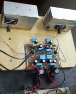
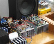
The amplifier, Circlotron modified....more Circlomanen than Circlotron
I do not loose time to build pretty things...i want to listen and to tweak for sonics...if really aproved, then i will think to produce boards and to assemble something less ugly.
Not made for beauty contests.... this is a real man amplifier.
regards,
Carlos
I do not loose time to build pretty things...i want to listen and to tweak for sonics...if really aproved, then i will think to produce boards and to assemble something less ugly.
Not made for beauty contests.... this is a real man amplifier.
regards,
Carlos
Attachments
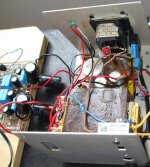
This is the Electronic, adjustable, stabilized power supply
It is a very old design from Ampex Video Tape..down the seventies...three transistors , one zener and some resistances... a trimpot to adjust voltage... some condenser to filter and to behave alike a capacitance multiplier... stable, around 5 percent losses of voltage...i am entering with 36 into one regulator (they were splitted..cutted into two halves to avoid common ground) and entering with 30 volts into the other.
The output was adjusted to 23.5 volts each one of those supplies.... 1.4 amperes adjusted each amplifier side.... off set is 22 milivolts.
The supply has only 6600uf each one of them into the input... the rectifier filter is this way...but the electronic supply cuts all possible ripple... the noises from mains disappear completelly...into the output i am using 22.000uf each regulator.
Works great.... i have tried 2.8 amperes and both ones have losses...voltage droped to 23.2 in one of them and 23.0 into the other... so..i have re-adjusted to the idle current (1.4 amperes) and them, adjusted under load conditions, with amplifier on, sucking energy, the voltage was the same both amplifier sides.
The input is a splitter...phase is changed from colector to emitter...then you have the audio inverted to feed one and other amplifier inputs (I hope i am doing correctly this)
The input circuit uses a single BC547 transistor... colector and emitter resistances the same value (470 ohms).... and 100K goes from the base to ground...VBE is bigger than 630 milivolts (good)... and the circuit is powered using 3 plus 3 volts battery, to simetrical supply... this is to reduce noises...the consumption there is small, so the batteries will last for monthes... the amplifier will not last for week.
regards,
Carlos
Attachments
I have used the transformer normally used to my bench supply
Normally use as 36 plus 36 volts...but i have removed connections and used the 36 plus 36 that resulted 36 rectified and filtered.... three wires...two diodes into the rectificaton and the center tape as negative...so....diodes joined together i have as result a single supply.... 36 volts and zero!
Another coil, that has no connection with that 36 volts, only leaves into the same transformer, was rectified, this time using full wave bridge, because two wires coil..and them i have 30 volts.
These voltages received 6600uf of filtering each one and was sent to the adjustable electronic regulator adjusted to 23.5 volts each one or the supplies into the output terminal from the regulator..the energy to feed the amplifier.
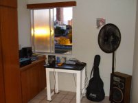
Here is the transformer.... over it some plastic material not to have rust (not epoxi...it is something alike rubber)
regards,
Carlos
Normally use as 36 plus 36 volts...but i have removed connections and used the 36 plus 36 that resulted 36 rectified and filtered.... three wires...two diodes into the rectificaton and the center tape as negative...so....diodes joined together i have as result a single supply.... 36 volts and zero!
Another coil, that has no connection with that 36 volts, only leaves into the same transformer, was rectified, this time using full wave bridge, because two wires coil..and them i have 30 volts.
These voltages received 6600uf of filtering each one and was sent to the adjustable electronic regulator adjusted to 23.5 volts each one or the supplies into the output terminal from the regulator..the energy to feed the amplifier.
Here is the transformer.... over it some plastic material not to have rust (not epoxi...it is something alike rubber)
regards,
Carlos
Attachments
Well folks.... i go doing and doing...i just cannot stop to assemble things
curiosity is the hell of my life!
Today..or tomorrow, i will publish here the electronic supply schematic.
Very old, very good, very reliable.
Hiper Super, double Guaranteed!
If speed is good.... do not know!... no amplifier have complained to me since i started to use this...down the seventies.
regards,
Carlos
Attachments
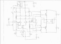
Here is the supply.... you need only to build two to use into Circlotron
Of course you can build two using complementary transistors... the one is show will receive positive to upper left side..using NPN transistor (all power transistors will fit)....to the output you can use 1 , 2, 3 or many transistors in parallel...and the power will be your transfomer power and the heat will be your consumption generating heat..so...heatsink will depends on your use.
Building another one, with PNP transistors.... a mirror version of this one...with negative down the page..you will be able to joint those two supplies to produce a simetrical adjustable, stabilized, electronic power supply.
The NPN negative line will be connected to the PNP supply positive line...and this connection will constitute your ground..of course this will came from rectifier and filters from a three wires secondary.
You can see two resistances marked as 1K5 and 1K5... this is good to voltages up to 45 volts..if you will input 65 volts..then use 2K7 and 2K7 instead of those 1K5 ones.
If you gonna input lower voltage..lets say 35 volts...them you can reduce to 820 ohms plus 820 ohms.
The minumum adjustable voltage is the zener voltage more the junctions you have in series (each one produces zener effect of 600 milivolts)...if you reduce this zener you will be able to adjust 4.7 volts and even lower voltages (using 1N4002 instead of zener..this diode must be assemble with the arrow inverted when reference is the zener arrow position).
If you will input 20 volts, for instance and will have 10 volts into the output..then use 4V7 or 3V3 zener.... use 470 ohms resistance in the 1K5 place and be happy my friend.
Each ampere will need 5000uf into the output to good results into power amplifiers...BUT...if you install only 100uf will work fine too....ahahahahah!
Into the input, the rectifier...there you will need 2200uf each ampere for audio quality... the electronic filtering offered by the electronic stabilizer circuit reduces the need of too much big condensers.....it does the work to "erase", to finish, to delete, to remove any listenable ripple can bother your amplifier sonics.
Guaranteed...works great...can use other transistors..the ones you love.... good idea is to use to220 into the error amplifier position (the trimpot position)... also TO220 into the first series pass transistor you have into the darlington (those two output units are assembled alike a darlington..of course a real darlington or many darlingtons can be used.
Use stronger ones into the output... and remember... not more than 30 watts to each one of your output transistors..this is a safety measure..to avoid to lost transistors.
The power the series pass transistor will face will be the colector voltage minus the emitter voltage (output voltage adjusted) multiplied by your consumption.
So...lets say you will input 65 volts...and will adjust to 45 volts..and 4 amperes will be needed each side...so... 65 minus 45 is equal to 20 volts....multiplied by 4...then you have 80 watts of heat there... two or three transistors will do this job safely.... and this to each rail.
regards,
Carlos
Attachments
There's something strange into the sound... i quit
I really do not feel it good enougth...seems compressed.... the treble is there, but seems a little bit mufled (I have removed all capacitors.. tried the unit without them).
Bass is not strong enougth.
Very hot.... very low power.... no good to me.... yes... sound is good.... but has not life!...something strange and loud... seems excess of signal, i have tried to reduce sensitivity almost everywhere..... i could not.
Back to AB
I quit!
regards,
Carlos
http://www.youtube.com/watch?v=Xt86ofe7o_s
Attachments
Carlos, I guess it is better to remove the input stage that you have included and use either something like an Aleph P 1.7 which would allow for unbalanced IN and Balanced OUT or atleast a good quality op-amp to provide the balanced drive function.
Driving the input phase splitter with +-3Volts and the rest of the amp at a higher voltage will certainly reduce dynamics. Moreover, CBS240 had already mentioned the phase related problems with the single transistor phase splitter.
Check out http://sound.westhost.com/project87.htm, http://sound.westhost.com/project51.htm and use one of these balanced drivers for a start.
Being a relatively low wattage amplifier, the Cyclotron would require fairly sensitive speakers which may not be the case with the ones you are using. Another reason could be that the Damping Factor may be very low, while you may be used to a relatively high DF amp.
I'd encourage you to try using a better phase splitter and perhaps a single driver to get a taste of Class A.
I agree with Bonsai above. My experience with these kinds of amps is that cross-coupled feedback helps improve performance, especially at high levels. It also reduces dependence on class A operation, so you may find that you can back off on the output stage bias a bit and still get good sound.
Carlos, your latest schematic shows two independent signal feedback paths, with 10 ohms and 3300uF in series with each JFET source. You can convert this to cross-coupled feedback by removing these four components and then adding 39 ohms (or whatever gives the desired closed-loop gain) directly across the JFET source terminals.
Carlos, your latest schematic shows two independent signal feedback paths, with 10 ohms and 3300uF in series with each JFET source. You can convert this to cross-coupled feedback by removing these four components and then adding 39 ohms (or whatever gives the desired closed-loop gain) directly across the JFET source terminals.
I have tried several class A amplifiers during my long life
I thank you by the advices and suggestions..but i have quit.
Cannot have gain into the input... sensitivity there is already enormous, even reducing the gain into the feedback network..so..no chip amplifier into the input... even with gain one it will produce noise...and noise into sensitive amplifiers is a hell.
No more try.... it is enougth to me.
No more class A amplifiers... they are almost the same... and really not very good to my ears.
Maybe my taste is some distortion....or at least the most common ones.
I will not feed this thread anymore... all questions i had to myself were answered..and unfortunattely i was rigth about all of them... a pitty that... i would be more happy if wrong.
I am already dismounting the unit.... some good parts to keep with me...and listening a good bootstrapp amplifier that is driving me happy once more... not a tiring amplifier.
The other one created me two main pleasures... first when i switched it on... the hope to sound interesting...and was interesting..but not the "interesting" i like... the second pleasure was when i switched the unit off... this sound is a hell tiring.
Also i perceive that happens usually that Class A lovers blame my speaker, my construction, my phase inverter, my supply, my transformer, my home, my cat, my dog, my wife, my appartment, my ears...well... they cannot accept someone not loving class A.... and some of them are really crazy.... some of them have never tried to compare and go with those beliefs that one class is better than other.
I do not "think" things folks...i do tests...many comparisons...i know how sounds.... i believe nothing.... about those Class A i was trying once again... exercising my "not belief"..... unfortunattelly the result is always the same.
Good, very good, but hot, mufled, tiring audio.... without power...drives me tired.
Be happy with your class A amplifier folks...maybe is better this way.... some folks do not compare... and this is interesting...as we go living thinking we have the best.
regards,
Carlos
I have invited children.... boys and girls... they have no knowledge nor preferences
They understand nothing about sound...just young kids and some teenagers.
I was testing my results.... i have played to them Symassym adjusted to 8 watts... the same power was adjusted the Circlotron - Circlomanem - Dx modified.
Many musics were played... a single speaker used.
Symassym is not the best in trebles i have at home..i have others with more treble (perceived level and quality)...my Symassym is not the last model...there are one more modern i am not using.
7 to 1 was the score..... Symassym was the winner.
I have just informed:
"A" is playing!
now "B" is playing!
"B" was symassym... the winner.... then i have asked then why?
answer:
- the other one (Circlotron) is mufled... seems we have carpet (other one said pants... and another said pillow) atop the speaker, covering and reducing something... they said sound is good...but Symassym is much better.
I agree.
No pictures... children parents do not want pictures into the internet...i do not know why...but i have to respect.
You may say...your tweeter may be no good!... well..it is good to Symassym....if i change to a better tweeter, even this way the treble will be better to Symassym... and this one, the Symassym is not the best one in trebles i have in my home.
This has nothing about measurements...nothing related flat or unflat!...this is dinamic behavior, interaction with speaker, power transmission, power transference, impedance adapting, damping.... the Circlotron, into Simulator was better than Symassym...real life was not!
regards,
Carlos
Hi Carlos
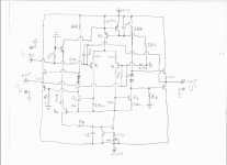
Before this thread dies and is buried in the endless pages of dead and rotting threads, I was thinking.....a bit outside the box……and have an idea to run by you. The question is, 'will it work?'. The idea is to use common mode error correction to create two balanced signals, with gain. Then use source following outputs with gate drivers.
Theory: When a signal is applied to the + input of the differential, there will be two outputs. The + output is fed back to the - input and the - output is fed back to the + input, i.e. added (subtracted) to the input signal. The + input has 9/10ths of the positive phase signal, and the - input has 1/10th of the positive phase signal as feedback from the positive output. Since the differential amplifies the difference, the ‘negative output’ becomes the negative phase. But, the magnitudes will be unequal if Ra = Rb. If Ra is a smaller value than Rb, the positive output Z becomes lower, requiring more current for Q3 than for Q4. This will produce a varying common mode current in the VAS differential, related to the difference in current out from the + output wrt the - output causing the voltage across the current source at the top to vary proportionally. This change in common mode voltage is sensed by Q5 and fed back to the bottom CCS, Q6, actively balancing the common mode current in the VAS differential via the first LTP (Iy) so that the common mode current is always equal to the CCS at the top. Since the - output is smaller in magnitude, the modulating drive it receives at the source of Q2 will increase the - output wrt to the + output to the same voltage level as the + output, with the right value resistors. Follow each output by a buffer and the difference in output Z disappears, or rather becomes insignificant to the transfer function. If the common mode error amp has good GBW, it should be able to keep up even with frequencies well above audio band. By having the top CCS slightly variable aught to set the DC output voltage wrt the VAS collector resistor values, close to 0 VDC. As far as transistor count, , but you certainly need a lower Z drive for the gates of the output fets, IMHO.
This is all bit of speculation….
This is a variation of a certain bridge circuit that I made and to be fair it's gain is only 5 instead of 10 or 20. In the bridge, the CCS needs no pot, as the CCS current does not define the DC output voltages. I haven't built this version yet:, I just thought it up. If I do (don’t have the time now) the top CCS current would be defined by the collector resistor values and supply voltage. I think the output stage arrangement is neat....if it will work.
EDIT: THen again maybe I just had too many beers to the head, eh?
Oh yeah, don't forget the zeners to protect the mosfet gates.

Before this thread dies and is buried in the endless pages of dead and rotting threads, I was thinking.....a bit outside the box……and have an idea to run by you. The question is, 'will it work?'. The idea is to use common mode error correction to create two balanced signals, with gain. Then use source following outputs with gate drivers.
Theory: When a signal is applied to the + input of the differential, there will be two outputs. The + output is fed back to the - input and the - output is fed back to the + input, i.e. added (subtracted) to the input signal. The + input has 9/10ths of the positive phase signal, and the - input has 1/10th of the positive phase signal as feedback from the positive output. Since the differential amplifies the difference, the ‘negative output’ becomes the negative phase. But, the magnitudes will be unequal if Ra = Rb. If Ra is a smaller value than Rb, the positive output Z becomes lower, requiring more current for Q3 than for Q4. This will produce a varying common mode current in the VAS differential, related to the difference in current out from the + output wrt the - output causing the voltage across the current source at the top to vary proportionally. This change in common mode voltage is sensed by Q5 and fed back to the bottom CCS, Q6, actively balancing the common mode current in the VAS differential via the first LTP (Iy) so that the common mode current is always equal to the CCS at the top. Since the - output is smaller in magnitude, the modulating drive it receives at the source of Q2 will increase the - output wrt to the + output to the same voltage level as the + output, with the right value resistors. Follow each output by a buffer and the difference in output Z disappears, or rather becomes insignificant to the transfer function. If the common mode error amp has good GBW, it should be able to keep up even with frequencies well above audio band. By having the top CCS slightly variable aught to set the DC output voltage wrt the VAS collector resistor values, close to 0 VDC. As far as transistor count,
, but you certainly need a lower Z drive for the gates of the output fets, IMHO. This is all bit of speculation….
This is a variation of a certain bridge circuit that I made and to be fair it's gain is only 5 instead of 10 or 20.
In the bridge, the CCS needs no pot, as the CCS current does not define the DC output voltages. I haven't built this version yet:, I just thought it up. If I do (don’t have the time now) the top CCS current would be defined by the collector resistor values and supply voltage. I think the output stage arrangement is neat....if it will work. EDIT: THen again maybe I just had too many beers to the head, eh?
Oh yeah, don't forget the zeners to protect the mosfet gates.
Attachments
I am waiting a big protoboard...then i will be able to try
Please, without hurry, produce other schematic with all values there.... resistances values calculated to 35 volts positive and 35 volts negative ... seems simetrical, but not sure...i have to study the schematic and i have just take a look on it.
In on month, i hope, i will have protoboard...so....during this lapse of time you may be able to complete the schematic.
You ideas are always interesting..... and i will give a try on it...but with protoboard that i will find easier..... as layed down into the bed i can have the pleasure to assemble without the soldering iron burning the bed.
This is not a promisse that i will REALLY build...i am beeing honest with you...i am so tired... so deadly pizzzed with Class A that i would be glad to have the gun machine...that one can shot into a ratio of 600 rounds a minute and vaporize, desintegrate all Class A monsters i have at my home.... this gun machine sound is nice.... a hell deep 10 hertz... the devil's throat sound!
So...if has not time to spend producing a design, without guarantee that will be built by me, may be not interesting to you...and i will respect your decision.
panzertoo@yahoo.com
regards,
Carlos
Attachments
Hey!... hold on... i have no complementary fets
Can you produce the schematic using BGT only?
Those FETs...you know... they sound strange!
I have lateral fets to the output...but i have no small ones complementary...so.....i am impeached to build
schematics because of those complementary guys there.
I have build two amplifiers..single stage...class A... to compare FETs and transistors..... i like BGT the most.
No!... they do not sound the same... and those big Megahertz FETs can go does not appear into the music.... result the opposite.
Man!.. there are many Myths into our world....i would like to have Mythbusters visiting us... a pitty... this is something they will not be interested because are not "universal" myths.... would be interesting they testing "monster cables" and unobtanium golden yellow stripped magic powder burning in capacitors.
I am too much old... i cannot stand for those foolishes anymore.
ahahahahahahh!
regards,
Carlos
Hi Carlos
The circuit shows the idea, but the values depend on your specific component measurements. So is the way with J-fets. This may be a reason people don't like them. I don't see a reason why you could not use BJT's for the input transistors, Q1 and Q2. Also the dependent source, Q6, could probably be replaced by a 2 transistor CCS. BUT Q5 is required to be a fet because it must be a voltage controlled current device. BJT is current controlled so the base current will interfere with the set point of the adjustable CCS. If P-ch J-fets in Brazil are made of unobtainium, it should work both ways, i.e. reverse polarity of all devices. Could be fun to play with.
For +/- 35V, the collector resistors would have 35 V for output to be 0 V. If collector resistors are 22K, then each side conducts 35V/22K=1.6mA. If Q1 & Q2 are BJT's that bias 1mA each, the -CCS would be set to 5.2mA. For the positive, dependent CCS, 0.6V/2mA + 1mA for the J-fet, would have 200 Ohm resistor. The J-fet would have to be measured for Vgs @ 1mA to find Rc. Then Vgs/1mA=Rc. A very simple rig can be made using a 741 to measure Vgs.
I have to leave town for a few weeks but if you do decide to try it, my procedure for the bridge version is to set Ra = Rb until you get the DC bias correct and that all currents are within reason to what was calculated. Also a large gate resistor on the J-fet will help to keep the J-fet from reverse biasing until you get it balanced but isn't needed for operation. Input a signal and verify that you get 2 outputs, + phase and - phase, and that the - output is smaller than the +output. Then place another larger resistor in parallel to Ra and the -output should get larger wrt the +output. A scope would be handy, but if no access to one, maybe you could use 60-100Hz signal and DMM?
The PCB's for the project that the other circuit is in should be here today or tomorrow and I already have all the parts.....but I cannot do anything with it because I have to leave town. Maybe I will get to build it next month....
Hopefully it will work, at least as good as the UGLY AMP version does, but I won't know until then.
The circuit shows the idea, but the values depend on your specific component measurements. So is the way with J-fets. This may be a reason people don't like them.
I don't see a reason why you could not use BJT's for the input transistors, Q1 and Q2. Also the dependent source, Q6, could probably be replaced by a 2 transistor CCS. BUT Q5 is required to be a fet because it must be a voltage controlled current device. BJT is current controlled so the base current will interfere with the set point of the adjustable CCS. If P-ch J-fets in Brazil are made of unobtainium, it should work both ways, i.e. reverse polarity of all devices. Could be fun to play with.For +/- 35V, the collector resistors would have 35 V for output to be 0 V. If collector resistors are 22K, then each side conducts 35V/22K=1.6mA. If Q1 & Q2 are BJT's that bias 1mA each, the -CCS would be set to 5.2mA. For the positive, dependent CCS, 0.6V/2mA + 1mA for the J-fet, would have 200 Ohm resistor. The J-fet would have to be measured for Vgs @ 1mA to find Rc. Then Vgs/1mA=Rc. A very simple rig can be made using a 741 to measure Vgs.
I have to leave town for a few weeks but if you do decide to try it, my procedure for the bridge version is to set Ra = Rb until you get the DC bias correct and that all currents are within reason to what was calculated. Also a large gate resistor on the J-fet will help to keep the J-fet from reverse biasing until you get it balanced but isn't needed for operation. Input a signal and verify that you get 2 outputs, + phase and - phase, and that the - output is smaller than the +output. Then place another larger resistor in parallel to Ra and the -output should get larger wrt the +output. A scope would be handy, but if no access to one, maybe you could use 60-100Hz signal and DMM?
The PCB's for the project that the other circuit is in should be here today or tomorrow and I already have all the parts.....but I cannot do anything with it because I have to leave town.
Maybe I will get to build it next month....Hopefully it will work, at least as good as the UGLY AMP version does, but I won't know until then.
Attachments
- Status
- This old topic is closed. If you want to reopen this topic, contact a moderator using the "Report Post" button.
- Home
- Amplifiers
- Solid State
- Perfect sound search, this idea, HELP!, the long and insane search...