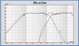
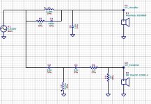
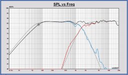
I have made a LR4 at 1500Hz, with the same filter configuration.
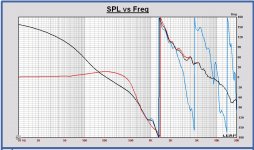
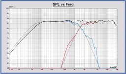
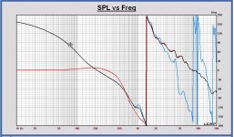
In the SPL plot, the LR4 targets are added, to see the deviation from target.
It is the best I can make with this configuration for the moment.
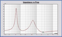
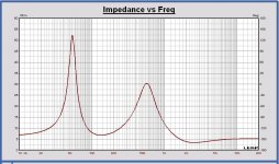
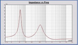
The minimum impedance is 3.5Ohm at 2.5kHz. F3 is 75Hz.
Serial resistance of coils: 3.9mH/0.30E and 0.270mH/0.82E.
To improve it to be better on target and have more low frequency extension, the filter has to become more complex.
F3 should be lower for this speaker IMO. Adding a port can also be an option.
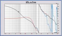
In attachement also the frd's of the drivers that I use in Leap.
In the SPL plot, the LR4 targets are added, to see the deviation from target.
It is the best I can make with this configuration for the moment.
The minimum impedance is 3.5Ohm at 2.5kHz. F3 is 75Hz.
Serial resistance of coils: 3.9mH/0.30E and 0.270mH/0.82E.
To improve it to be better on target and have more low frequency extension, the filter has to become more complex.
F3 should be lower for this speaker IMO. Adding a port can also be an option.
In attachement also the frd's of the drivers that I use in Leap.
Attachments
-
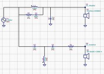
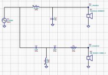 Mayuri filter V3 schematic.JPG126.9 KB · Views: 610
 -
Mayuri SB 26ADC-C000-4 Imp.txt19.4 KB · Views: 45
-
Mayuri SB 26ADC-C000-4 FR.txt22.2 KB · Views: 48
-
Mayuri Peerless 830869 Imp.txt19.4 KB · Views: 33
-
Mayuri Peerless 830869 FR.txt22.2 KB · Views: 23
-
 Mayuri filter V3 Impedance.JPG116.3 KB · Views: 307
 -
 Mayuri filter V3 phase.JPG187.6 KB · Views: 302
 -
 Mayuri filter V3 SPL.JPG182.7 KB · Views: 319
I really like Paul's improvements. Please notice the loss in efficiency, in exchange for bass extension down to 100 Hz. I think it could still be a little bright, but overall this is going to be a much better balanced system with or without a sub.
I also think maybe the OP should experiment with both and listen, it may help him better experience why we are making the suggestions we are.
Best,
E
I also think maybe the OP should experiment with both and listen, it may help him better experience why we are making the suggestions we are.
Best,
E
@ Erik
I also expect the sound of such speaker with F3 = 75Hz will be too bright, missing some fundament in the sound to be expected.
Designing the sensitivity to 84dB which is a normal value for this Peerless driver of 90dB, to compensate for the baffle step, will indeed decrease the F3. The problem I have already seen is the impact of the woofer impedance peak on the filter if the serial coil has to become higher. There will appear some boost. So the woofer impedance peak needs to be compensated with a RLC parallel on the woofer. I need then the value of the impedance peak.
@ Mayuri
You can easily measure the impedance peak of the woofer as follows.
A sine wave generator (50Ohm output impedance or lower), 1Vrms, and a serial resistance of 1k to the woofer. So an AC current of 1mA is flowing. Then you sweep by hand to the frequency where the maximal voltage on the woofer is reached. That voltage divided by 1mA gives you the value of the impedance peak and the frequency you can read on the generator. It is not 100% correct in this way, because the current will decrease a little at the peak, but it gives a good indication already.
Filling the cabinet will decrease the peak of course, if you want to apply some filling.
Your filter looks good Paul. Still quite minimalistic for LR4, so not a lot of cost in purchasing new components. I got quite a stack of crossover components, but unfortunately only the 2,2Ohm resistor and .27mH coil are in it.
F3 of 75Hz is something that a sealed cabinet just gives. I am quite content with it, because I will be crossing these speakers over to my Ripole subwoofers via a MiniDSP 2x4HD anyway. Porting is still an option, as this woofer has been succesfully been used in for example here:
http://www.diyaudio.com/forums/multi-way/316284-building-bookshelf-9.html#post5284603
I will measure the impedance peak tomorrow, assuming my NAD 912 can handle being the sine wave generator.
Paul: But for a satellite, F3 ~= 80 Hz is THX standard, so very much a typical value. My comments about brightness was more about the tweeter level. I might be tempted to bring it down 1-2 dB. I think that for the intended purpose however, you have struck the best balance of efficiency and bass extension already.
The woofer Z peak is fine, for solid state amps. Worth experimenting with, but attempting to completely fix it will require very large resistors.
Best,
E
The woofer Z peak is fine, for solid state amps. Worth experimenting with, but attempting to completely fix it will require very large resistors.
Best,
E
Last edited:
Erik, thanks ... indeed, with a subwoofer it has less sense to lower F3.
Mayuri also tells me, I didn't know") .
.
Concerning the tweeter response, I am not so happy with the tweeter SPL under LR4 target between 2 and 5 kHz in my last proposal. It becomes better by making the coil of the tweeter filter lower, but then the impedance becomes 3 Ohm at 2.5 kHz, that is low. I will look if there is no better solution for the tweeter, keeping it simple.
Maybe the tweeter level has to be 1dB down, I agree. Interesting to tune during listening.
I will have a look to the power response also.
Mayuri also tells me, I didn't know
.Concerning the tweeter response, I am not so happy with the tweeter SPL under LR4 target between 2 and 5 kHz in my last proposal. It becomes better by making the coil of the tweeter filter lower, but then the impedance becomes 3 Ohm at 2.5 kHz, that is low. I will look if there is no better solution for the tweeter, keeping it simple.
Maybe the tweeter level has to be 1dB down, I agree. Interesting to tune during listening.
I will have a look to the power response also.
Good tip Mayuri ... I have seen also in designs of Troels.
But you have to add a serial resistor also.
I have made an example, cap of 15uf changes to 12uF also.
But you have to add a serial resistor also.
I have made an example, cap of 15uf changes to 12uF also.
Attachments
Last edited:
Thanks for the simulations, they are very useful. Could you still simulate tweeter with 18uF and 47uF cap? I have these two in stock as good quality caps myself.
Will order the missing parts on monday so I can assemble the crossover and do some listening tests and measurements.
Will order the missing parts on monday so I can assemble the crossover and do some listening tests and measurements.
Maybe we have to design a more advanced filter also. With the drivers perfect on target, also far outband. Doing like that you realize a timing of the drivers conform the targets that you choose. In a digital filter it is possible, in a passive filter it can become very complex to realize it.
Mayuri, why don't you make a complete digital design with your miniDSP, also for the satellites.
Mayuri, why don't you make a complete digital design with your miniDSP, also for the satellites.
That would be optimal, but I want to keep the satellites passive for three reasons:
1) I need the MiniDSP for subwoofer EQ, crossover and level matching. The 2x4HD has only 4 outputs, so 2x subs + 2x satellites. My current satellites are ScanSpeak 10F/8424 in spherical enclosure.
2) In case I sell them, etc.
3) I want to try out passive crossovers
The raised baffle for woofer is still not out of the question to obtain physical time alignment for the drivers. Would be a trivial thing to add 21mm panel thickness as I plan on redoing the finish on the enclosures anyhow.
Last edited:
Thanks for the simulations, they are very useful. Could you still simulate tweeter with 18uF and 47uF cap? I have these two in stock as good quality caps myself.
Will order the missing parts on monday so I can assemble the crossover and do some listening tests and measurements.
Mayuri,
This is the best I can make with these components. I have to keep the impedance larger than 3 Ohm.
The targets are made 0.25 dB lower.
Attachments
paul, consider a small value ( < 2 Ohms) in series with the HP coil to help with the minimum impedance. Usually 0.5 to 1.0 is typical there.
Thanks Erik, that is correct I will have a look at it.
The serial resistor of the coil is already chosen 0.82 Ohm now, but I look if a larger value is maybe better.
The minimum impedance is now 3.0 Ohm
Paul
That wasn't very clear.
What I mean is, don't try to use the L-Pad to keep 4 Ohms. It is 100% OK if you increase the effective Tweeter Z by a few Ohms, so long as you hit your target dB level. Then re-calculate your HP filter accordingly. You can do this by changing the L-Pad to a single resistor, or by increasing the value of the shunt resistor.
I usually use a spreadsheet to help me get the right values of effective Z vs. level drop.
Best,
E
Last edited:
@ Erik
At first sight the serial resistor of the tweeter filter coil cannot be made larger, keeping the capacitor values the same like Mayuri asked me.
Increasing the resistor has a damping effect on the filter.
@ Mayuri
To remember you that I have chosen the coils: 3.9 mH/0.3 Ohm and 0.22 mH/0.82 Ohm.
I cannot visualize the serial resistor values of coils in Leap, it is a stupid package
- Status
- This old topic is closed. If you want to reopen this topic, contact a moderator using the "Report Post" button.
- Home
- Loudspeakers
- Multi-Way
- Peerless 830869 + SB26ADC-04 crossover help?