I have built two different versions, so far, and I also have Lazy Cat's modules from the GB in his VSSA thread. The one I listen to almost daily is the one closest to Shaan's original schematic (with compensation caps added, and a highly filtered power supply). I am still experimenting, but I do believe that this amplifier benefits from a clean supply, more so than others. I also hope to try some of the other versions, like Marc's (well, Borys/Marc's anyway...)
That one is one good looking and smooth amp! Well done.
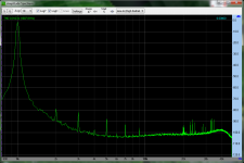
Today I captured the very first FFT of the real amplifier through my soundcard which supports 96KHz sampling. Below is the spectrum for 1KHz at 20V peak to peak onto 10R resistive load. The whole signal from the amp was attenuated to 1/10th values by a 1K+100R network (to prevent destruction of the line-in node).
The spectrum clearly proves one thing:- We are not prejudiced guys deluding over imaginary goodness; the level of quality is perceptible AND measureable.
The simple amp we are building is a nothing less of a masterpiece, build and listen to one for further "details".
YooHoo!!!

The spectrum clearly proves one thing:- We are not prejudiced guys deluding over imaginary goodness; the level of quality is perceptible AND measureable.
The simple amp we are building is a nothing less of a masterpiece, build and listen to one for further "details".
YooHoo!!!
Attachments

I have started my Peeceebee. I am using Rev 1.3 of the VSSA schematic. Input transistors are KSA992/KSC1845. These are the only transistors that I could get to match.
VAS transistors are BD139-16/BD140-16. Again these are the only ones I could get to match.
The LATFETs are in hand but not yet connected. I just want to understand the front end and driver biasing before I proceed.
My voltages are +/- 15 on the proto board. I changed 15K to 5K. All other passives are as per the schematic.
2.8mA through the PNP emitter. 3.0 mA through the NPN emitter. I changed the 470 ohm resistors to 1k pots to set the VAS transistors. Stock 470 ohm resistors caused 50 mA in the VAS transistors. I am dialing the 1k pots for 100 mV across the 10 ohm resistors.
Transistor pairs match are 1% to 2% at 30V and 2 mA for inputs and 10 mA for VAS transistors.
Question: In the V1.3 schematic, what should be the DC voltage to ground at the capacitor pair that grounds the connection of 47 ohm and 15k resistor?
Comments are encouraged.
On my board, that voltage is around 0.75V, with +/-35V supply, and 100R/2.2K....
Question: In the V1.3 schematic, what should be the DC voltage to ground at the capacitor pair that grounds the connection of 47 ohm and 15k resistor?
In any case, under 1V.
Could all four versions schematics be posted in one here?
Nope. The schematic for PeeCeeBee is fixed and is shown in the first post. Check the VSSA thread for all four schematix.

2.2K is your feedback resistance and 100R is the resistor from emitter to capacitor junction?
On my board, that voltage is around 0.75V, with +/-35V supply, and 100R/2.2K.
In any case, under 1V.
Question: In the V1.3 schematic, what should be the DC voltage to ground at the capacitor pair that grounds the connection of 47 ohm and 15k resistor?
It is the sum of the drop at input BJT emitter (~0.7V) and the drop at the 100R connected to its ground(will vary depending on input bias current if gain setting resistor is fixed). I biased the inputs in my boards a bit higher, so I have about 1.2V at the capacitor(s).
Correct. If you are making the effort to match your transistors, you should measure/match the opposing pairs of these resistors also.2.2K is your feedback resistance and 100R is the resistor from emitter to capacitor junction?
Since the feedback is effectively two parallel feedback circuits, a difference in the resistors will have an effect (I am sure Shaan will correct me if I am mistaken about that). In my next (and I hope final) build, I am thinking about using some kind of temp-stable resistor in place of the 2.2K 1%. (Assuming I ever get close complementary Transistors...
)Correct. If you are making the effort to match your transistors, you should measure/match the opposing pairs of these resistors also.
Since the feedback is effectively two parallel feedback circuits, a difference in the resistors will have an effect (I am sure Shaan will correct me if I am mistaken about that). In my next (and I hope final) build, I am thinking about using some kind of temp-stable resistor in place of the 2.2K 1%. (Assuming I ever get close complementary Transistors...
I have spent days measuring hundreds of transistors.
Just about every comp sets yield no matches. The only real matches I find are KSA992/KSC1845. It is particular tape and reel ones that match, not just any ones. BTW the PNPs are end-of-life. I am attempting to lay away a lifetime supply of matched pairs for when I have more time than money.
BD139/140-16s yielded 8 matched sets from 25 pcs of each.
I would be happy to trade some matched transistors for blank boards when you have your next batch fabricated.
Well I tried firing up my boards today without much luck. The first board started smoking the two 10R resistors behind the 4007s. The second one didn't smoke anything but it is pulling 140ma on the positive rail and has -.545VDC offset. I didn't have time to trouble-shoot but will try to get to it tomorrow. Does anyone have a voltage chart made up for this circuit? At least a ballpark of what I should be seeing at each of the transistors would be a big help.
Thanks, Terry
Thanks, Terry
Hello fellas,
This is one of the best threads on the forum at the moment. Real diy spirit!
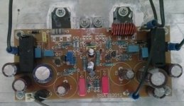
I´ve been lurking in this thread from the beginning and few weeks ago I built my own peeceebee. The schema is according to shaan, but the Rail caps are 1000uF for the fets and 100uF for the front end. My vas transistors are 2sb1109/2sd1609. comp caps were needed and with 22p the amp is stable.
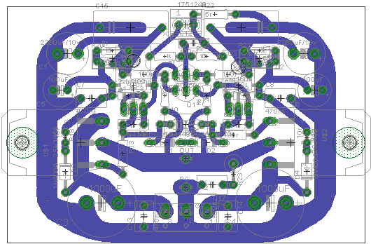
I also have slight hum when I put my ear on the speaker and it used to be much louder because of the pcb design. The pcb itself is a shameless copy from PMI:s work but not as good since I had hum.
The difference between the current implementation and the attached image is that I had to connect the input ground with a separate wire to the power ground to get rid of the hum.
I am drawing a new pcb soon...
This is one of the best threads on the forum at the moment. Real diy spirit!
I´ve been lurking in this thread from the beginning and few weeks ago I built my own peeceebee. The schema is according to shaan, but the Rail caps are 1000uF for the fets and 100uF for the front end. My vas transistors are 2sb1109/2sd1609. comp caps were needed and with 22p the amp is stable.
I also have slight hum when I put my ear on the speaker and it used to be much louder because of the pcb design. The pcb itself is a shameless copy from PMI:s work but not as good since I had hum.
The difference between the current implementation and the attached image is that I had to connect the input ground with a separate wire to the power ground to get rid of the hum.
I am drawing a new pcb soon...
Attachments
Sounds good to me,I would be happy to trade some matched transistors for blank boards when you have your next batch fabricated.
Imitation is another form of compliment......The pcb itself is a shameless copy from PMI:s work but not as good since I had hum...
The hum could be noise picked up on the input leads from the transformer secondary winding and leads. If I make a longer input lead with a half-loop, and hold it closer to the transformer, the noise I can see on the 'scope gets bigger. If I get close enough to the toroid, there is audible hum.
The circuit is fairly susceptible to this, in other words, it may not be the layout. Couple other people have noticed the same thing.
Terry,didn't you use a light bulb tester?
Yes and a variac. As a matter of fact, on the first one. I got it to about half voltage when the light bulb began to glow so I shut it down and noticed that I had the two 100uf caps reversed. I change them and started over. Before I got to 25V the bulb started to glow again and the two resistor began to lightly smoke so I shut it down and got out the other channel. I hooked up an ammeter to this one so I could watch the amp draw. This one would go all the way to full rail but drawing too much current and too much offset. It was late by then so I just shut things down. I would like to trouble shoot it tomorrow but need to know some voltages to look for.
Thanks, Terry
Any chance you might have the VAS transistors backwards, or swapped?Yes and a variac. As a matter of fact, on the first one. I got it to about half voltage when the light bulb began to glow so I shut it down and noticed that I had the two 100uf caps reversed. I change them and started over. Before I got to 25V the bulb started to glow again and the two resistor began to lightly smoke so I shut it down and got out the other channel. I hooked up an ammeter to this one so I could watch the amp draw. This one would go all the way to full rail but drawing too much current and too much offset. It was late by then so I just shut things down. I would like to trouble shoot it tomorrow but need to know some voltages to look for.
Thanks, Terry
The only current that should go through the 10R at idle is the VAS bias plus front end bias. There should be minimal voltage across the 10R. Around 0.1~0.3V, before the bias and offset are adjusted.
Good call Pete. I just went and checked and on the one that smoked the 10Rs the ;BD 139 and 140 are swapped. That's one of the problems with trying to build stuff when I don't have all the parts. I get out of sequence. Man, I hope I didn't hurt them. I'll swap them in the morning and go from there.
This brings up the next issue. You mention adjusting the bias. How do you do that on the Shaan boards when there are no pots?
Thanks, Terry
This brings up the next issue. You mention adjusting the bias. How do you do that on the Shaan boards when there are no pots?
Thanks, Terry
hi still4given
here is the procedure written by shaan.. it is somewhere here but could not remember the page
1. A digital multimeter.
2. 1R/1W x 2.
3. 22R/2W x 2.
For first time power-up solder two 22R/2W resistor to the PS rails, one end of each of them to each rail. Connect the PS to the open ends and turn on power. If nothing explodes/smokes then replace both of the 22R with 1R/1W and connect the PS again, but don't power it up instantly.
Take notes for the measurements from now on.
Set your digital meter to 'mV' and connect the probes to both ends of one of the 1R resistors. Turn on power. Check meter reading. That number shows total Quiscent current Iq.
Measure the front end plus VAS current I(f v) by probing the voltage at the ends of the 10R after the 4007 diodes.
Measure VAS current I(vas) by probing the voltage at the ends of the 10R at their emitters.
Now,
Total current= Iq
Front VAS current= I(f v)
VAS current= I(vas)
So, from aquired data we get,
Front end current= I(f v) - I(vas)
and
FET current= Iq - I(f v)
I hope this will be helpful.
- Home
- Amplifiers
- Solid State
- PeeCeeBee