If one decide to use 10k log pot at the input, can 10k input resistor be replaced with higher value (22-47k) and will it change the performance of amp in any way?
Yes it can be done. I would suggest 47 k in such case, since wiper to GND resistance of 10 k log pot will be paralleled with this resistor. Common parallel resistance would in this case changed from zero Ohm to 8,2 k max.
Performance of the amp will change a litlle, since passive atenuator always lowers input impedance and because of enlarging input serial resistance also decrease low pass filter's bandwidth.
In this case it is always better to use input buffer, to adopt source and amp's impedances.
")
AC on the output when the input is shorted is noise.
It can be hum and/or white noise.
Try loading the input with different resistors. I keep dummy load RCA's for just this testing: 0r0, 100r, 1k, 10k, 100k in pairs. Use cheap plastic RCA plugs.
AC noise on the output is not output offset.
DC on the output is output offset.
Oppss missed this one...
Sorry still newbie here..correction acknowledged.
Thank you for pointing that out.
Regards!
Would it be beneficial to use additional capacitance between gate and source of N channel Lateral MOSFET to make it more similar to P channel and therefore make amp more stable or these things are not important with CF topology?
Would this trick be better than using compensation caps on VAS transistors (in case of oscillation)?
Would this trick be better than using compensation caps on VAS transistors (in case of oscillation)?
Would it be beneficial to use additional capacitance between gate and source of N channel Lateral MOSFET to make it more similar to P channel and therefore make amp more stable or these things are not important with CF topology?
Would this trick be better than using compensation caps on VAS transistors (in case of oscillation)?
Just in case i think you can use small caps on vas transistors.
I my case I had some small problem with hum noise becouse speaker cables were twisted together.
As LC (BIG THANKS) said put speaker out cable away from rest of the cables.
My amp is rock solid. I have changed 15k resistors with 18k and vas bias is 10ma to 14ma, output offset is 0,8mV, output bias is 100mA stable.
Amp is playing day and night to get bed in (amp is at work so can play whole night no problem
)Regards
Ps
O scope on output I have no oscillations at all.
Hello friends. 
About two weeks ago I got some serious illness that initially gave me a 104deg fever for two days and extreme throat irritation for about a week thereafter, most probably it was the effect of the sudden extremely hot weather. As a result I just couldn't sit in front of the PC and post a single thing. All I could do was to scan the diyaudio pages occasionally from my cellphone, which doesn't allow me to post anything in any forum threads(!).
However, I am back, and am feeling well now. How are you people? I am very happy to see the thread going on and you guys keeping up the good job of spreading the fun. You rock!
10uF at input. No need to bypass with any other cap.
Hey man that's superduper kool!
No need for G to S cap. But compensation caps are a good idea to tame it when you get HF oscillation. My peeceebees are stable, so I don't use any of these caps.
You guys are very very kind. But these boards are for my own and local friends' amp jobs only and will(should) not be made available for group buys. Cause explained below.
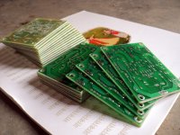
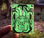
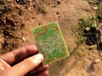
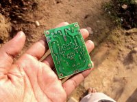
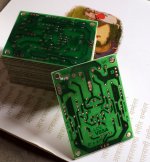
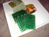
And here they are(although very late).
As you can see the boards look pretty cool(well, to me at least). But there are some printing faults by the etching guys(it was a cheap job anyway).
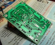
Problems: there are some jumbled prints on the silkscreen side of the larger fonts and the solder mask isn't perfectly aligned with the outline of the board(however, the pads are well surrounded and are error free b.t.w., also the parts fit exactly as planned ).
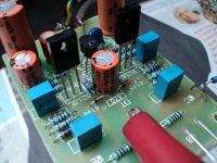
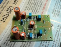
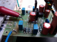
I have populated two of the boards and the first had 5mV offset and the second now has 11mV, without manual setting, stable. And as usual with an SSA, the boards are singing all day long, still naked.
shaan
p.s.: Hi Andrej. Thank you for the support while I was off. You are kind as always.
About two weeks ago I got some serious illness that initially gave me a 104deg fever for two days and extreme throat irritation for about a week thereafter, most probably it was the effect of the sudden extremely hot weather. As a result I just couldn't sit in front of the PC and post a single thing. All I could do was to scan the diyaudio pages occasionally from my cellphone, which doesn't allow me to post anything in any forum threads(!).
However, I am back, and am feeling well now. How are you people? I am very happy to see the thread going on and you guys keeping up the good job of spreading the fun.
You rock! good afternoon, Mr.Shaan, lazycat. ssa, VSSA capacitors1uf or 10uF input section? I want to put in bypass use 10uF capacitors size value how? 10uF bypass 0.1 uF ... can not like that on VSSA and amplifier ssa ..
10uF at input. No need to bypass with any other cap.
Here's my first two TO3 PeeCeeBee's. Will begin to populate them with parts on hand very soon.
Hey man that's superduper kool!
That is the amp anyway.
Would it be beneficial to use additional capacitance between gate and source of N channel Lateral MOSFET to make it more similar to P channel and therefore make amp more stable or these things are not important with CF topology?
Would this trick be better than using compensation caps on VAS transistors (in case of oscillation)?
No need for G to S cap. But compensation caps are a good idea to tame it when you get HF oscillation. My peeceebees are stable, so I don't use any of these caps.
Can I get one pair of these boards?
shaan,i want get one pair the peeceebee shaan vssa
Shaan...i loved to have too
Please can I request you for a pair?
gannaji
You guys are very very kind. But these boards are for my own and local friends' amp jobs only and will(should) not be made available for group buys. Cause explained below.
Pix will be uploaded soon.
And here they are(although very late).
As you can see the boards look pretty cool(well, to me at least). But there are some printing faults by the etching guys(it was a cheap job anyway).
Problems: there are some jumbled prints on the silkscreen side of the larger fonts and the solder mask isn't perfectly aligned with the outline of the board(however, the pads are well surrounded and are error free b.t.w., also the parts fit exactly as planned
).I have populated two of the boards and the first had 5mV offset and the second now has 11mV, without manual setting, stable. And as usual with an SSA, the boards are singing all day long, still naked.
shaan
p.s.: Hi Andrej. Thank you for the support while I was off. You are kind as always.
Attachments
-
 DSC08912.JPG428.4 KB · Views: 818
 -
 DSC08937.JPG744.6 KB · Views: 292
 -
 DSC08936.JPG549.9 KB · Views: 277
 -
 DSC08935.JPG399.7 KB · Views: 305
 -
 DSC08933.JPG426.6 KB · Views: 311
 -
 DSC08923.JPG560.9 KB · Views: 306
 -
 DSC08921.JPG566.6 KB · Views: 651
 -
 DSC08920.JPG905.4 KB · Views: 688
 -
 DSC08918.JPG493.2 KB · Views: 717
 -
 DSC08916.JPG474.1 KB · Views: 764
p.s.: Hi Andrej. Thank you for the support while I was off. You are kind as always.
We're here to support and help each other, it was all my pleasure Shaan.

Do you guys at all aware how quality the sound reproduction from this amp can be?
Try to find some really good speakers like KEF R700, FOCAL Scala or better and good .wav audio source and you'll be amazed.

P.S. Do anybody knows where's Esperado, miss him for a while.
Hmmm, I think I see the idea for a new signature line: "My other speakers are Focal Scala"!Try to find some really good speakers like KEF R700, FOCAL Scala or better...
Posted by shaan "You guys are very very kind. But these boards are for my own and local friends' amp jobs only and will(should) not be made available for group buys. Cause explained below."
Can you kindly give contact details of the PCB supplier and Semiconductor suppliers in India?
--gannaji
Can you kindly give contact details of the PCB supplier and Semiconductor suppliers in India?
--gannaji
hehe just like some fancy plates: "My other car is Ferrari"Hmmm, I think I see the idea for a new signature line: "My other speakers are Focal Scala"!
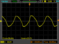
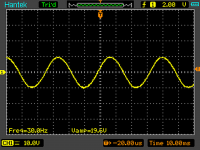
I found small problem with my amp, distortion in low freq.
Supply is 80W transformer 68V (both rails together on iddle), load is 8R.
Supply is dropping to 66V and 65V (both rails)
Take a look at around 30-35W 30Hz sin output.
THX
Supply is 80W transformer 68V (both rails together on iddle), load is 8R.
Supply is dropping to 66V and 65V (both rails)
Take a look at around 30-35W 30Hz sin output.
THX
Attachments
I found small problem with my amp, distortion in low freq.
Supply is 80W transformer 68V (both rails together on iddle), load is 8R.
Supply is dropping to 66V and 65V (both rails)
Take a look at around 30-35W 30Hz sin output.
THX
Few possible reasons:
- too small value of FB coupling elcos, they should be 2200 uF/6,3 V
- not enough drive current, VAS bias should be 12-15 mA
- bad output mosfets, too low transconductance
Few possible reasons:
- too small value of FB coupling elcos, they should be 2200 uF/6,3 V
- not enough drive current, VAS bias should be 12-15 mA
- bad output mosfets, too low transconductance
Thanks Ill check and let U know.
Does not seem right... if 80W means 80VA total power, and 68V == dual 34V secondary winding, this would not be enough power for two channels at 8R nominal load, especially for a test at low frequency.Supply is 80W transformer 68V (both rails together on iddle), load is 8R.
Do the two pics show a distorted signal on the left, and an un-distorted signal at lower amplitude on the right?
A continuous signal at low frequency is pretty much a worst case test for system limited by power supply capacity. So as the amplitude of the test signal increases, the demand on the power supply exceeds the capacity of the transformer, the magnetic field starts to collapse, ...etc.
I found small problem with my amp, distortion in low freq.
THX
Are mosfets originals? High price of lateral mosfets = high motivation for some people to fake them.
I think fault is with my laptop crap sound card. I repeted measurement of input to amp and it looks exacly the same - I have to buffer or preamp the input to amp.
It's nothing wrong with your sound card, just needs bigger coupling capacitor on its outputs. Look inside PC, track down output capacitors on both channels of the sound card and replace them with 10 times higher values as they're now.
- Home
- Amplifiers
- Solid State
- PeeCeeBee