It's nothing wrong with your sound card, just needs bigger coupling capacitor on its outputs. Look inside PC, track down output capacitors on both channels of the sound card and replace them with 10 times higher values as they're now.")
Thanks LC
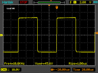
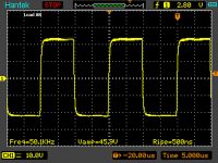
I have made some measurements today, and do not know why
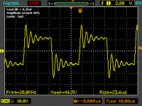
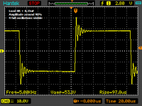
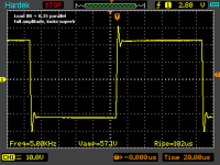
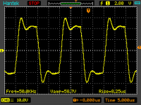
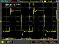
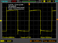
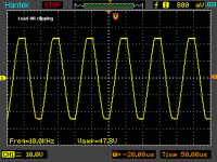
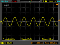
on full amplitude everything looks very very good, but with lower amplitude pulse response is getting worse - is this normal ?
Load is 8R + 0,35uF. There was no input cap fitted on measurement.
My amp is mada according shan schematic (resistor values + no 22p caps in VAS stage) THX
Attachments
-
 vssa.png119.2 KB · Views: 904
 -
 vssasqtr3.png143.6 KB · Views: 121
 -
 vssasqr6.png128.2 KB · Views: 115
 -
 vssasqr5.png122.6 KB · Views: 113
 -
 vssasqr4.png131.9 KB · Views: 105
 -
 vssasqr2.png131.8 KB · Views: 115
 -
 vssasq1.png129.6 KB · Views: 804
 -
 vssaclipp.png149.3 KB · Views: 830
 -
 vssa50khz.png129.1 KB · Views: 854
 -
 vssa1mghz.png132.6 KB · Views: 886
Have you fitted a Zobel or a Pi network to see if that helps?
There is no zobel fitted, just bare two laterals and two 0,1R resistors
There is no zobel fitted, just bare two laterals and two 0,1R resistors
hahaha you would expect better without output filters (zobel + pi), without regulated bias spreader and without CCS, no way. For a sch you've built you've got superb results

There is no zobel fitted, just bare two laterals and two 0,1R resistors
Hi borys.
First, remove both 0.1r resistors, these things there can cause interesting and weird problems and the blame will be put on the amp as a whole, as usual.
If you are using 1k/47r in fb network then increase them to 2k2/100r and check the output. If still no good then install Cdom and zobel and check again.
If none of the above helps then install the CCS which will make the amp a superfast rocket. Then give it a ride and see if the journey is smooth enough.
If still too shaky then the problem is either in the PS or the signal source/input cable.

Thanks for help.
I have 2,2k/100r at the moment.
I will try some modyfications at the weekend.
So basicly everythink is working fine - thanks for replay.
LC
I do not expect anything more (it is very very good rigt now), just want to make sure that I have assebled the amp properly.
Only what I am not sure is 3 last pictures, If there is a way to improve not full amplitude response to make it look like full amplitude (full is excellent).
Thx
Hi Naf,Hi LC and Shaan could I use sk163 as CCS?
Thanks.
I guess we can use K170 as CCS, but for sure wait for others says...
I'm still gathering parts, not complete yet
Already have hfe = 600+ for NPN input tr but no PNP.
Regards
TeeOhThree PeeCeeBee lives!
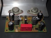
Well, there are no errors on the board or in the construction. TeeOhThree PeeCeeBee is officially alive!
I have a little offset to trim away and I need to increase my output bias. The offset is from my completely un-selected components and the really low bias was me just being cautious.
They play music however, so once the details are sorted I can give them a go on my main speakers to see how they actually sound.
Well, there are no errors on the board or in the construction. TeeOhThree PeeCeeBee is officially alive!
Congratulations! They look great!
Steve.
Congratulations! They look great!
Steve.
Thanks. I don't work fast but I think it came out quite nice. The circuit doesn't exhibit any discernible hiss or hum and powers up cleanly. I need to get the heat sinks mounted to the adapter brackets and get both channels hooked up and playing together. Next step will be a dedicated PSU and some DC detect speaker protection.
Faster than I do (chuckle). I just got my boards this week, and still taking inventory of some odds and ends.Thanks. I don't work fast...
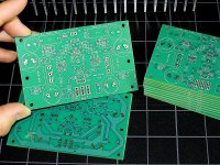
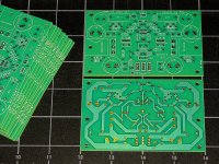
Progress (Finally)
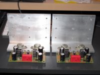
I finally got my boards and most of the parts to assemble and test... and, many thanks to those who helped to get this far,
In case the pics are confusing, the layout IS single layer, all circuit traces on the bottom of the board, silk screen on the top, all through-hole parts, most components on top, 2SK1058/J162 on the bottom. However, the boards were fabricated as if 2-layer, with plated holes and solder mask on both sides.
Attachments
Hi,
Could I buy a pair of your pcbs?
Thanks.
... not tested yet... you may want to wait until I build one, and make sure it does not catch fire, . After that, sure.
Ok, I'll wait
Thank you.
This is an excellent way to design a PCB................the layout IS single layer, all circuit traces on the bottom of the board, silk screen on the top, all through-hole parts, ........ However, the boards were fabricated as if 2-layer, with plated holes and solder mask on both sides.
Now that PTH and double layer PCBs are affordable, I wish more would do it this way.
@AndrewT: I was happy with the way it turned out, given that I wanted to get more than a couple pieces at a low cost. The plated-through holes help (in my case, at least), b/c pads don't detach if I have to de-solder a component. Also, there is some flexibility in soldering on top or bottom for ease of access.
@Jkueteman: I used "Rush PCB" in San Jose, California, first time for me, but recommended by someone else. (RushPCB.com) If you plan to do this a few times, there is no substitute for a friendly local source, but my usual contact was not available to do a small run. Circuit boards are a funny business. You have to be willing to make a few phone calls, and not take it personally when someone quotes high. Usually you can find a company that will bundle your prototypes with a larger order from someone else, but you may have to live with a 2-week delivery time. Also, taking the time to learn how to use a Gerber file viewer to check the layout one layer at a time against the board outline and against the silkscreen helps avoid mistakes you won't see otherwise. Seems like a waste of time in the beginning, but you get to appreciate it if you find a mistake.
@Jkueteman: I used "Rush PCB" in San Jose, California, first time for me, but recommended by someone else. (RushPCB.com) If you plan to do this a few times, there is no substitute for a friendly local source, but my usual contact was not available to do a small run. Circuit boards are a funny business. You have to be willing to make a few phone calls, and not take it personally when someone quotes high. Usually you can find a company that will bundle your prototypes with a larger order from someone else, but you may have to live with a 2-week delivery time. Also, taking the time to learn how to use a Gerber file viewer to check the layout one layer at a time against the board outline and against the silkscreen helps avoid mistakes you won't see otherwise. Seems like a waste of time in the beginning, but you get to appreciate it if you find a mistake.
- Home
- Amplifiers
- Solid State
- PeeCeeBee