Any suggestions on the heatsink? Do you think thermal coupling the drivers will make any difference here?
I don't expect any sonic difference
") . Sharing a common heatsink is good as it will help keep the offset stable even more. But make sure to connect the heatsing to ground. Otherwise oscillations might occur.
. Sharing a common heatsink is good as it will help keep the offset stable even more. But make sure to connect the heatsing to ground. Otherwise oscillations might occur.shaan
Sorry shaan, I'm beginner in using toner transfer method.
No no! I don't mean that it's "bad" in any way! I'm a lover of ugly diy jobs; 'been making great amps in rough way for years. here you can take a look at my veroboard thread -> Post Your Vero Designs Here
Yes it beats my Denon!
Of course it does!

vssa is very clean compare to Denon.
And to many other commercial offerings too!
I only use 2 4700uf in power supply. Shaan, is there improvement if i used recommended power supply?
A simple dual supply is enough. For good bass and overall better LF transient response, use more than 10000uF per channel per polarity if possible.
shaan
Here my sa970/sc2240 version...Hi naf, yeah, i fully satisfied the quality of sound of vssa. Can you share your 2sa/2sc peeceebee version? It hard to obtain here in our local electronic store bc550c/bc560c. Thank you in advance.
Regards,
Boyet
credit goes to LazyCat and Shaan for sharing enjoyment among us
Attachments
Here my sa970/sc2240 version...
credit goes to LazyCat and Shaan for sharing enjoyment among us
Thank you very much naf your sa970/sc2240 version.
Thanks,
Boyet
I forgot to say...
WELCOME to the thread daudio!!!
shaan

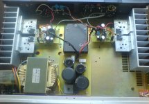
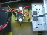
Here is another rude example of DIY. Regulated PSU.
I have 3x SSA stereo amps for my 3 way speaker active setup.Now i changed one for tweeter to VSSA.It's hard to judge as it's been only few hours of listening,but on tweeter i definately like VSSA more.And definately it is very very good (i'm sure someone would call it hi end) sounding amp.
Thank yo shaan for supporting underground movement
and Lazy Cat for sharing his knowledge with DIY comunity.
Attachments
I think I need another clue here (sorry). I understand how removing the resistor changes the bias current, but how do you "set" the output bias current to a specific value, given the different rail voltages people are using?Congrats naf.
Remove that 470ohm parallel to the diodes and you'll get ~170mA.
...
shaan
With the two diodes and the resistor most application will result into a bias of about 100mA.
Removing the resistor will increase it to the bias that 1.4V between the FETs' gates allow, which is between 150mA to 180mA.
For lower bias remove the resistor plus the diodes and place a single diode in place of the resistor, you'll get about 45mA of Iq.
For higher bias remove the diodes only and carefully experiment and set the resistor value that gives you the desired Iq, OR, put more diodes in series with the existing diodes and remove the resistor.
Important: removing the diodes will result into output bias's direct dependence on VAS bias; i.e. Iq will increase slowly as the VAS stage heats up and draws a little more current.
For most applications the two diode bias setting will be perfect(and somewhat safe; those FETs are quite expensive).
shaan
I'm wanting to build the peeceebee version of the VSSA, but I want to use three power supplies, for the three sets of transistors. I would like to use ±42 volts (30volts rectified) for the Vas, and ± 35 volts (25 volt rectified) for the output stage.
Is there any problem with using the peeceebee circuit as is, with ±42v on the Vas stage. I'm building four amplifiers (2 x stereo) on vero board using discrete ALF 08 N 16v and ALF 08 P 16v transistors.
[Input transistors will be fed by very low noise regulated supplies, around ±12v]
Is there any problem with using the peeceebee circuit as is, with ±42v on the Vas stage. I'm building four amplifiers (2 x stereo) on vero board using discrete ALF 08 N 16v and ALF 08 P 16v transistors.
[Input transistors will be fed by very low noise regulated supplies, around ±12v]
Last edited:
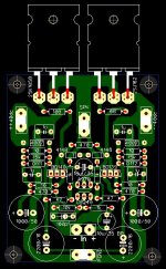
After much shuffling of components here's where my TO-3 version sits...
Looking good!
Some non-critical, non-expert suggestions:
1) Could the two 1uF caps on each side be aligned to be parallel? (i.e. rotate the one sitting 'east-west' so they both sit 'north-south')
2) Could the trace from the 2000 uF cap up to the 1000 uF cap be thinner?
3) Is there enough room between the edge of the TO3 heatsink and the v+, V- and speaker out connectors?
Steve.
I like it!After much shuffling of components here's where my TO-3 version sits...
- Home
- Amplifiers
- Solid State
- PeeCeeBee