Yes. Just checked. They are correct, identical to good channel.
Also, I was testing all the ground points on the circuit, doing a continuity test from the psu input ground pad and I found a few issues. C3 ground pin was not soldered properly. Input ground wire was not soldered properly. Repaired. Hum has gone way down, only slight hum with volume fairly high, probably because of how it is rigged on the bench.
Still have oscillation problem at R16/R17. I will give it a break and swap Q4, Q5 tomorrow.
Thanks for the help.

Start at the beginning, the voltage around Q3 is wrong, once sorted move on to the hum problem.
In Wayne's circuit the JFET's are drawing 20mA, bnorrish your circuit is drawing 28mA, adjust the value of R9 to 330R or 360R to compensate 10V/0.28mA=~360R.
Seberia has the same problem.
Do you have hum at the collector of Q3?
Didn't Wayne mention way back in this thread that R9 was part of the RIAA network and should be left alone?
Can higher Idss of the quad at the input really have much impact on the second stage? I have no audible problems with mine, I'm only having a bit of trouble with the 0V dc setting (mostly the right channel). I can get it to wander fairly close around 0V, but if you measure again next day miost of the times it has wandered off, to something like 300mV (I power down the unit at night btw, only measuring after it has been on for at least an hour).
Changing the 10R to 12R would get my quad down from 27,5mA to 23mA, 15R would get it to 18,5mA. But if this lowers the gain of the first stage I will have to compensate that in the second stage as I like a bit more gain than the standard 55dB.
Make sure to buy her some nice records to keep her interested. Joni Mitchell, Carole King, Cat Stevens in my case.")
Ha, if only--for my wife it would have to be Tool, and their vinyl costs a mint. It would make her happy, though, so I will probably do it.
Ha, if only--for my wife it would have to be Tool, and their vinyl costs a mint. It would make her happy, though, so I will probably do it.
Your wife is coooool and I'm jealous!
PS You better hold on to that one! She's a keeper!
I know, I am lucky. She took me to see Tool when she was 8 months pregnant with our first child. He is only ten months now, but thankfully seems largely free of angst. We will see.
Hi folks. I have decided to give this a try, and have begun to order parts. I am a genuine beginner--my only electronics experience up to this point came from owning an Italian motorcycle, whose electrical system was (predictably) crap, and fried. I taught myself to solder and got it back on the road, but it was more just following instructions than genuinely understanding what was going on (lots and lots of info out there on fried Italian motorcycle electrical systems). I have bought a few "learn to solder" boards to practice on, and hopefully will get comfortable with it when I have the parts to begin.
I am planning to start with the power supply, and following the example of budwiser, as pictured in post 1387 and discussed in post 1480. I am trying to map the power supply design to the schematic, and have a few questions right off the bat. Some are very basic, for which I apologize.
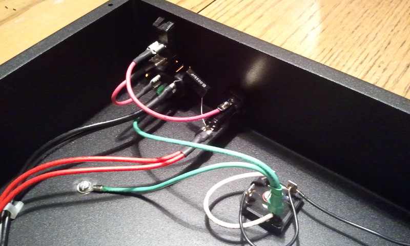
In reference to the following picture: http://www.diyaudio.com/forums/atta...d1329711222-pearl-two-2012-02-19-22.59.04.jpg
Am I thinking of this right: what I see is the connector to the power cord on the bottom left, with the pink cable going up to the power switch, which is connected to an LED (?not sure of this?), which is connected to the fuse on the schematic (?). This is connected, along with the black wire, to C1 (?).
First really dumb question: why do the red and black wires actually have two wires (besides that is what comes with the transformer)? How do you know which wire to hook up the capacitor to?
Small question: in this picture, what is the little thing called that allows you to make four connections, bolted to the case (it makes the wiring neat, I haven't been able to find one because I am not sure what it is called): http://www.diyaudio.com/forums/atta...d1329711222-pearl-two-2012-02-19-22.58.43.jpg
Last questions (for now, I imagine!): does it matter whether you use male or female jacks for the XLR? Can someone suggest a similar case?
Thanks very much for any responses, and thanks for all the work you have done communicating on this topic. I would never try this if not for this thread. Just so you know, I am looking to replace a Phonomena with this, and have a Lyra Dorian cartridge.
Thanks again!
Hi folks. I have decided to give this a try, and have begun to order parts. I am a genuine beginner--my only electronics experience up to this point came from owning an Italian motorcycle, whose electrical system was (predictably) crap, and fried. I taught myself to solder and got it back on the road, but it was more just following instructions than genuinely understanding what was going on (lots and lots of info out there on fried Italian motorcycle electrical systems). I have bought a few "learn to solder" boards to practice on, and hopefully will get comfortable with it when I have the parts to begin.
I am planning to start with the power supply, and following the example of budwiser, as pictured in post 1387 and discussed in post 1480. I am trying to map the power supply design to the schematic, and have a few questions right off the bat. Some are very basic, for which I apologize.
In reference to the following picture: http://www.diyaudio.com/forums/atta...d1329711222-pearl-two-2012-02-19-22.59.04.jpg
Am I thinking of this right: what I see is the connector to the power cord on the bottom left, with the pink cable going up to the power switch, which is connected to an LED (?not sure of this?), which is connected to the fuse on the schematic (?). This is connected, along with the black wire, to C1 (?).
First really dumb question: why do the red and black wires actually have two wires (besides that is what comes with the transformer)? How do you know which wire to hook up the capacitor to?
Small question: in this picture, what is the little thing called that allows you to make four connections, bolted to the case (it makes the wiring neat, I haven't been able to find one because I am not sure what it is called): http://www.diyaudio.com/forums/atta...d1329711222-pearl-two-2012-02-19-22.58.43.jpg
Last questions (for now, I imagine!): does it matter whether you use male or female jacks for the XLR? Can someone suggest a similar case?
Thanks very much for any responses, and thanks for all the work you have done communicating on this topic. I would never try this if not for this thread. Just so you know, I am looking to replace a Phonomena with this, and have a Lyra Dorian cartridge.
Thanks again!
As far as I can reply: on the left is a switch I think. Red wire comes from the mains socket, goes to the switch and the pink wire (=overexposed red) then goes to a fuse. A small black capacitor (3.3nF) can be seen from black wire to the fuse. This capacitor is also in the PSU schematic in the Pearl II article. Two red and black wires probably because of 2 120V windings from the transformer. No LED, the LED will be powered by the DC voltage of 28-35V (and protected by a resistor)
Male and female jacks: choose male for the jack/chassis part that does not carry voltage when you can touch it. So the mains input on the PSU chassis can be male, the mains jack on the mains cable then is female, or you would be in real danger of electrocuting yourself. The DC out chassis part (PSU) is female, the DC in chassis part (on the Pearl II) is male, cable plugs for the DC cable of course the opposite sex from the chassis parts...
Male and female jacks: choose male for the jack/chassis part that does not carry voltage when you can touch it. So the mains input on the PSU chassis can be male, the mains jack on the mains cable then is female, or you would be in real danger of electrocuting yourself. The DC out chassis part (PSU) is female, the DC in chassis part (on the Pearl II) is male, cable plugs for the DC cable of course the opposite sex from the chassis parts...
Using budwieser's example of PSU is fantastic. It is very well done... emulate what you see there and you should have no problems.
As for your questions, they are not dumb. The only dumb questions are the ones you don't ask.
Dual red/black wires. These are the transformer primaries, the ones that attach to the wall. (The secondaries are the wired that attach to the rectifier and PSU, and are usually a different voltage than the primary) The reason for the 2 wires is so you can attach them in paralell for 120v input from the wall (North America and other places) or in series for 240v from the wall (Europe, etc...)
The Secondary wires are the ones that you attach to the rectifiers/capacitor/etc -- the PSU. Which leads are which should be clearly marked on the transformer itself.
You say you are a beginner, and that's awesome! There are lots of people here who will be happy to help. The Pearl isn't really an ideal project for a beginner, but, if you take your time and are super careful, it will be fine. This is a circuit that need patience during construction no matter who you are. The rewards are that it's amongst the very best phonostages I have ever heard. Seriously, it's that good.
Anyway - please read every word of this webpage --
Building a Gainclone chip amp power supply.
Although this is specific to Gainclone powersupplies, there is tons of fantastic information that applies 100% to the Pearl PSU. It will clear up many of your questions. The unregulated Pearl PSU is basically a gainclone PSU with a smaller transformer...
The screw terminal thingy you asked about is called a Barrier block, screw terminal barrier block, terminal block, or some other variation of those words.
I swapped out Q4 and Q5. I can now easily tune P16/P17 to around +/- 50 mv of 0 V. I swapped back in the 499R at R28 instead of the POT. Connected to the TT and amp and I now get music. It sounds good on my cheap test system. I think I am good.
One thing to note. When I was trimming P1 with the amp board on the bench, I did not have TT hooked up at input or output to amp and I was getting wild voltage oscillations at P16/P17. Hooking up to the TT and amp (while on) made it more stable to trim P1. Does this make sense? You should only trim with input and output connected some sort of load?
One thing to note. When I was trimming P1 with the amp board on the bench, I did not have TT hooked up at input or output to amp and I was getting wild voltage oscillations at P16/P17. Hooking up to the TT and amp (while on) made it more stable to trim P1. Does this make sense? You should only trim with input and output connected some sort of load?
The Beginner's Climb to The Pearl2
The Pearl2 can be tricky, especially that second stage discrete opamp.
That's why I'm getting there in steps ...
http://www.diyaudio.com/forums/anal...l2-pcb-but-havent-started-yet-pearl1-5-a.html
And if you want, you can build in small successful steps:
The Beginner's Climb to The Pearl2
1) 1 JFET input, RIAA network, 1 JFET output and batteries ('pacific' or 'boozehound' style) easy as pie! Actually pie is hard compared to this ... seriously that easy (and safe, just batteries)!
2) Get AC and 24V chip power-supply working (careful and safe with AC)
3) Beef up the input with 4 JFETs in parallel and cascode (sort of Pearl1)
4) Beef up the output with 2 JFETs in parallel and cascode (Pearl1.5)
5) Add negative supply and beef up the output with discrete opamp (Pearl2)
All on the Pearl2 PCB (and matched FETs) to make sure you're doin' it right and you upgrade one project rather than building many (no 'wasted time' or v1.1 boards).
It starts easy and safe--perfect for the beginner--but you're also up and running (no long, boring learning curve) and enjoying your own phonopre! This satisfaction is overwhelming!
Listening to a proto-Pearl before even touching AC!
Then slowly and safely upgrade, climbing to the sublime summit of the Pearl2!
Oh ... and that connector is called a terminal strip/block, a screw-down terminal strip/block
...
You say you are a beginner, and that's awesome! There are lots of people here who will be happy to help. The Pearl isn't really an ideal project for a beginner, but, if you take your time and are super careful, it will be fine. This is a circuit that need patience during construction no matter who you are. The rewards are that it's amongst the very best phonostages I have ever heard. Seriously, it's that good...
The Pearl2 can be tricky, especially that second stage discrete opamp.
That's why I'm getting there in steps ...
http://www.diyaudio.com/forums/anal...l2-pcb-but-havent-started-yet-pearl1-5-a.html
And if you want, you can build in small successful steps:
The Beginner's Climb to The Pearl2
1) 1 JFET input, RIAA network, 1 JFET output and batteries ('pacific' or 'boozehound' style) easy as pie! Actually pie is hard compared to this ... seriously that easy (and safe, just batteries)!
2) Get AC and 24V chip power-supply working (careful and safe with AC)
3) Beef up the input with 4 JFETs in parallel and cascode (sort of Pearl1)
4) Beef up the output with 2 JFETs in parallel and cascode (Pearl1.5)
5) Add negative supply and beef up the output with discrete opamp (Pearl2)
All on the Pearl2 PCB (and matched FETs) to make sure you're doin' it right and you upgrade one project rather than building many (no 'wasted time' or v1.1 boards).
It starts easy and safe--perfect for the beginner--but you're also up and running (no long, boring learning curve) and enjoying your own phonopre! This satisfaction is overwhelming!
Listening to a proto-Pearl before even touching AC!
Then slowly and safely upgrade, climbing to the sublime summit of the Pearl2!
Oh ... and that connector is called a terminal strip/block, a screw-down terminal strip/block
Last edited:
Hi 6L6,
thanks for the link about building the PSU - I will have a closer look - 'cos my Pearl 2 has a wonderful "hum" sound
Not sure why this is, but that's only half the fun, finding out the problems and trying to solve it, isn't it?
Probably I did not get the earthing right and have a ground loop. Will sort it out...
How are you guys doing it? Do you have signal ground and enclosure ground completely seperated? And if not - is it connected through a 10 Ohm resistor and 0,1 uF capacitor? What about the connection amp enclosure to PSU enclosure? Does that need to be chassis-wise connected, so that the amp enclosure is also earthed? Signal ground also connected to amp chassis ground?
Thanks
Poli
I did the grounding like the article. Earth ground from the mains connected to the chassis of the PSU. Signal ground in the PSU connected to the chassis via the bridge. Only the PSU is connected to a wall socket with earth ground, other components are not (not really usual for audio equipment over here to have earth ground).
0V (signal ground) in the Pearl II enclosure is star grounded to a single point on the chassis. RCA inputs are floating from the chassis.
This way I have no hum whatsoever.
0V (signal ground) in the Pearl II enclosure is star grounded to a single point on the chassis. RCA inputs are floating from the chassis.
This way I have no hum whatsoever.
Poli - Regarding the earthing the basic layout is this -
PSU is only chassis attached to AC Mains earth. PSU ground (at capacitor) is attached to earth via the rectifier block as loop-breaker.
ALL connectors on RIAA chassis (RCA, phono ground post, PSU umbilical) are not connected to chassis. Both PCB grounds connect to phono ground post. Phono ground post connects to chassis via a wire only if that is quieter than floating it. (In both my pearls, it is quieter to connect to chassis. According to Wayne, thins isn't always the case, you need to try both ways.)
And lastly, the transformer (I.E., PSU chassis) needs to be 3 feet (1M) from the RIAA to be truly silent.
Check out my awesome drafting program --
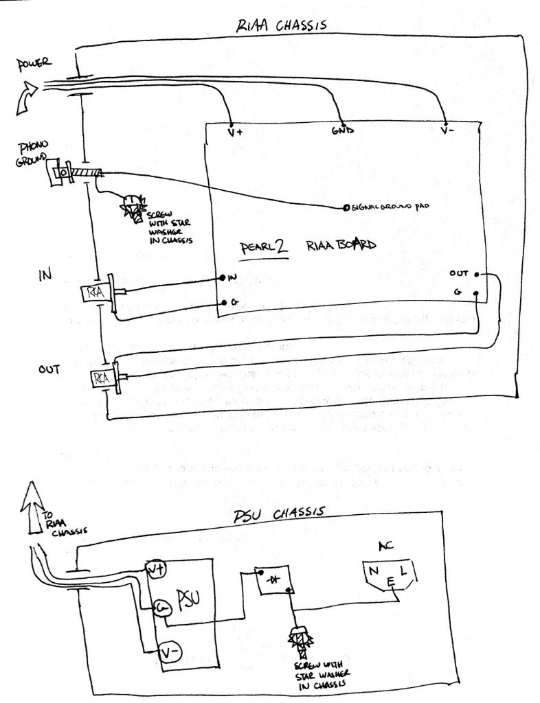
The important thing to remember is that all the connectors are floating. Ground them to the screw in the chassis only as you need to. (which will likely only be 2 things, the AC mains earth/ground breaker bridge, and the phono ground post.)
The important thing to remember is that all the connectors are floating. Ground them to the screw in the chassis only as you need to. (which will likely only be 2 things, the AC mains earth/ground breaker bridge, and the phono ground post.)
Last edited:
One chassis, actually quite similar, but the phono ground post would attach to the loop-breaker bridge, and the PSU likely wouldn't.
It wouldn't be very quiet with the transformer in the same box. Just getting a cheap plastic radioshack box to mount the transformer remotely would solve the problem. Have the rest of the PSU on board. Both the Pearl and the Pearl 2 are not truly quiet until the transformer is 3ft away.
It wouldn't be very quiet with the transformer in the same box. Just getting a cheap plastic radioshack box to mount the transformer remotely would solve the problem. Have the rest of the PSU on board. Both the Pearl and the Pearl 2 are not truly quiet until the transformer is 3ft away.
Last edited:
- Home
- Amplifiers
- Pass Labs
- Pearl Two