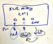
@mhenschel confirming your observation that my little diagram is wrong -- the signal identiification and pin numbers are correct, but I had indeed switched "shield" and "white".The balanced output connectors (CN1) aren't labeled, so I had to (gasp) squint at the circuit diagram to figure out how they're wired up. (It's V+/V-/Ground, or pin 2/3/1, FWIW).
The corrected summary: V+/V-/Ground -- pin 2/3/1 -- red/white/shield.
Thanks again for catching this, and I'm very glad I didn't connect it to my preamp this way!
Attachments
@ekobi
You're welcome.
Actually, while you're rewiring... I'm also unconvinced about the correctness of wiring pin 1 to the signal ground on the board... theoretically it should connect to the chassis directly and by a short conductor.
In practice -- according to all reports -- grounding seems to be as much "art" as science. Conventional wisdom is to try different schemes and use the one that works best in your particular situation.
Let us know what works for you.
The power supply with LM7915/LM7815 is going to be stable. There are no decoupling capacitors specified in the design.I would try other opamps for experiment. Also experiment with the overall gain. More gain should increase stability margin. Stability of the power supply and decoupling capacitors should be checked.
It's somehow caused by the preamp. Changed it for another and all seems fine. Thanks for your help 😃.This kind of susceptibility in my experience is usually caused by insufficient stability margin. The circuit doesn't oscillates but has a huge HF peak in the frequency response. As a result, it produces HF burst when triggered by sharp edged signal.
How much gain is set?
The power supply with LM7915/LM7815 is going to be stable. There are no decoupling capacitors specified in the design.
There are decoupling capacitors on the PCB at the op-amp power supply pins.
Hello sagittariusx,
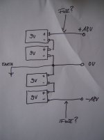
sure, you can use batteries to drive the PEARL 3. But you have to arrange them, that you get a symmetrical
voltage out of your batteries (easy).
From your voltage reference (0 V / ground) 2x 9V batteries in series (=+18 V DC) for the positive voltage and 2x9V batteries in series (= -18 v DC) for the negative voltage. The voltage regulators on the PEARL 3 boards do the rest.
I have done this a few times with phono-pres with very good (silent) results...
Cheers
Dirk
But is it audibly quieter than a well grounded P3 w/ Randy's PS?I have done this a few times with phono-pres with very good (silent) results...
It's an easy experiment, try it yourself and listen for differences.But is it audibly quieter than a well grounded P3 w/ Randy's PS?
While I understand and appreciate where you are coming from, I have so many projects in the works that I am not looking to add more. If there is a meaningful improvement... I am doubtful, largely based on faith in Wayne's design chops that he would have minimized noise. I realize this is largely a subjective evaluation w/ many variables, speaker efficiency being a big one. Oh, by the way my Pearl is sitting waiting for me to get started on the build, somehow an Aleph J jumped to the front of the assembly lineIt's an easy experiment, try it yourself and listen for differences.
")
That's how I do it. I need to get the stuff to do it correctly.@Craigl59 In 1 of the threads I posted a tip for soldering SMDs and some others posted other suggestions. Can't find the posts now, but a fellow on YouTube lightly tins 1 pad, flux is an essential soldering aid, then hold the SMD in place with a tweezer and heat the solder till it bonds, then solder the other leg and retouch the first 1.
I stand correctedThere are decoupling capacitors on the PCB at the op-amp power supply pins.
We were using helping hands and bamboo shiskibob sticks on the BA 2018 line stage....A couple of thoughts about how I have done this little solder job.
Preparation:
Clean the PCB down to the shine with 90-99% alcohol.
Snip off the roll of solder 0.81MM Dia. or smaller 1MM long bits of solder.
Have on hand:
tweezers
Tooth picks or orange sticks.
Solder flux paste
Procedure:
Apply flux paste to the PCB solder pads.
With the tweezers place the FET on the PCB
Push the FET into place with the tooth pick or orange stick. Motor control is much more precise with the tooth pick than your feigner tip.
Hold the FET in Place with the tooth pick or orange stick.
Push a clipped off piece of solder next to (touching) the solder pad and FET leg. One little piece of solder is all that is needed.
Heat the joint with the tip of your soldering iron.
Watch the solder melt and draw by capillary action into the joint.
Remove the soldering iron tip from the joint.
Move the toothpick away from the FET.
Wash Rinse Repeat
Examine your work with a loupe.
Thanks DT
Wait, I was supposed to actually Read The Fine Manual???Regarding XLR wiring - refer to the build doc. Here are a few screenshots.
Sigh. I don't know how I missed this.
Excellent point. I ended up running shielded twisted pair from the pads to the connector; shield floating at board, but wired to pin 1 & case of connector; and connector pin 1/case wired to rear panel grounding post. I also wired the power connector shield to the rear panel binding post to eliminate mains hum.Actually, while you're rewiring... I'm also unconvinced about the correctness of wiring pin 1 to the signal ground on the board... theoretically it should connect to the chassis directly and by a short conductor.
In practice -- according to all reports -- grounding seems to be as much "art" as science. Conventional wisdom is to try different schemes and use the one that works best in your particular situation.
Let us know what works for you
As an aside, I was relieved to confirm that that the differential line driver chips survived being shorted to signal ground for a couple of hours.
The balanced outputs? Great! More precisely, to my ears they work exactly as well as the RCA outputs. I did a relatively brief A/B test by dialing in a 6dB boost on the RCA input to the HPA4 (actually a bit complicated, since the RCA inputs are automatically boosted by 15.8dB, but not important). Over the course of about half an hour, even though I knew which input was playing at any given moment, I really could not hear any qualitative difference between the two. I've been listening to the balanced outputs for much of the weekend, and am pretty confident that they're sonically equivalent to the RCA outputs.and the proof of the pudding?
How'd it work?
My sense is that the only compelling reason for populating the XLR line drivers is to accommodate long cable runs between the phono stage and preamp (which is my justification). It obviously also frees up an RCA input on the preamp, which could be important, I suppose.
- Home
- Amplifiers
- Pass Labs
- Pearl 3 Burning Amp 2023