You are right Zoran it is the Zapfilter I will see today hopfully if at 0db what if anything is reaching it's head room.
Why I wondered about series resistance helping is because the designer of the Zap suggests to leave in the 33ohm resistors on each output of Sony balanced current output dac's, I wondered what this was doing?
Cheers george
Why I wondered about series resistance helping is because the designer of the Zap suggests to leave in the 33ohm resistors on each output of Sony balanced current output dac's, I wondered what this was doing?
Cheers george
Attachments
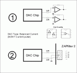
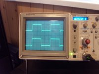
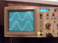
Here are the pics from the output of the Zap a bit blurred with no flash, shaky hands , I will try to get what's coming out of the dac chips while it is still attached to the Zap, another day.
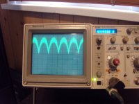
1: 1K 0db square wave
2: 1k -10db sine wave
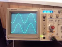
3: 1k 0db sine wave ( note the rounding of the top & bottom esspecially the top)
Cheers George
1: 1K 0db square wave
2: 1k -10db sine wave
3: 1k 0db sine wave ( note the rounding of the top & bottom esspecially the top)
Cheers George
Attachments
This is the pic of the same 1k 0db sine wave from the output of the dacs chip pin 13 still wired up to the input of the Zap.
It seems that the crows probe is loading it up, tried 1x & 10x probe setting but the same result. Also note the frequency counter is not right even thou it's supposed to be 1k
BTW the 0db 1k sines in the other pic were giving 8v p to p
Cheers George
It seems that the crows probe is loading it up, tried 1x & 10x probe setting but the same result. Also note the frequency counter is not right even thou it's supposed to be 1k
BTW the 0db 1k sines in the other pic were giving 8v p to p
Cheers George
Attachments
Everyones asleep on that side of the world.
Anyway as an experiment I did put a 100ohm resistor in series with the output of the 4 parralelled dac chips (pin 13) and guess what guys, it did drop the at the zaps output by 2v, and the sine wave of 1k a 0db looks just fine now, just like the -10db one.
Either the dac did not like the load it saw of the transimpedance amp or the transimpedance amp or it's output stage was overloading which I doubt because the zap when it clips looks much more savage across the top of sine waves than a slight rounding, it goes flat.
Any answers to this one?
Cheers George
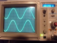
Here is a pic of the sine wave of 1k 0db but now with the 100ohm in series on the dac output before the input to the zap the output is 2v down from 7v from 9v compared to no resistor (pic 3), note the cal knob for voltage verification.
Now gone is the slight disortion I heard, esspecially on hard hit higher notes of a grand piano which had a slight ringing over tone that wasn't natural, now pure and clean.
Cheers George
Now gone is the slight disortion I heard, esspecially on hard hit higher notes of a grand piano which had a slight ringing over tone that wasn't natural, now pure and clean.
Cheers George
Attachments
Bernhard said:Isn't 9Vpp a bit much ?
I think the circuit is not designed for 4mA.
Perhaps it would sound even better if you bring down the output voltage further.
Maybe Bernhard, but it's good to have this 7v low impedance (50ohm)output, with my Lightspeed Attenuators as they are passive, and it gives me mid position for good normal level listening.
I wish I could somehow find out whether it was the dac or the Zap that was overloading, I have my suspicions it was the dac as the Zap hard clips at it's max output this was more like soft clipping with the rounding of those sine waves.
I have put these zaps on AD1955's and have never stuck this kind out overload, they are in there specs 8.64mA p to p diferential output, I don't know how that equates to the PCM56 4mA, they seem to have the similar output after the Zap has been instaled, this is why I supect the PCM56 as the AD1955 does not seam to have this slight overload problem.
Cheers George
Cheers George
Also Bernhard, I have about 4" of fine sheilded silver mic cable between the output of the dacs and the input of the Zap, which end is the best to put the 100ohm series resistor?
BTW can anyone sim the zap I haven't got or have the first clue how to use one, the transistors I know are all suppose to be Zetec which ones I don't know as all the numbers are not there.
Cheers George
BTW can anyone sim the zap I haven't got or have the first clue how to use one, the transistors I know are all suppose to be Zetec which ones I don't know as all the numbers are not there.
Cheers George
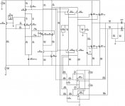
Bernhard said:that schematic says 1mA
That could be just what he tested at?
Cheers George
George,
This is for the schematic in post #52.
I did not simulate it, so no guarantee, please somebody correct me if I'm wrong.
The upper current source of the input stage has 0,6V across R1, that gives 6mA.
Per leg of the input stage that is 3mA.
If you want to sink 4mA with the DAC chips, you get current imbalance on the legs.
The voltage on the input node drops below 0V and Q1 which is biased -0,6V on the base for 0V on the input node, will stop conducting.
So the voltage on the upper node of R4 will clip.
On the other hand, if the DAC sources 4mA into the input node, that is no problem because the currents just add up.
That's why the clipping is asymmetrical.
Now why does the circuit not clip anymore if you add 100 ohm ?
The DACs should still sink 4 mA with the Resistor in series.
Answer is, they don't.
The 1mA @ FS is only valid for Iout connected to ground.
I found that 1K for I/V resistor does not give 1V but less.
The series resistor reduces the "full scale" and "per bit" current swing of the DAC and prevents the I/V converter from clipping.
It is clear that you will get a voltage swing on the DAC output if you add the series resistor because the input node is kept at 0V and there is the I*R voltage drop on the series resistor.
But as this is a good DAC") it doesn't matter.
it doesn't matter.
I think, if you do not want the series resistor, you could increase the bias of the ccs if you also adjust the zener D1 voltage to avoid a shift of the operating points.
The circuit clips at -3mA when the base-emitter difference of Q1 drops below 0,6V.
Anyway, I would use a pure resistive I/V stage, filter the signal, and if you need 7V, add a buffer with gain.
In that case, no active circuit would have to deal with the staircase signal.
I know, it is nice to have some sophisticated circuits but you just don't need it.
This is for the schematic in post #52.
I did not simulate it, so no guarantee, please somebody correct me if I'm wrong.
The upper current source of the input stage has 0,6V across R1, that gives 6mA.
Per leg of the input stage that is 3mA.
If you want to sink 4mA with the DAC chips, you get current imbalance on the legs.
The voltage on the input node drops below 0V and Q1 which is biased -0,6V on the base for 0V on the input node, will stop conducting.
So the voltage on the upper node of R4 will clip.
On the other hand, if the DAC sources 4mA into the input node, that is no problem because the currents just add up.
That's why the clipping is asymmetrical.
Now why does the circuit not clip anymore if you add 100 ohm ?
The DACs should still sink 4 mA with the Resistor in series.
Answer is, they don't.
The 1mA @ FS is only valid for Iout connected to ground.
I found that 1K for I/V resistor does not give 1V but less.
The series resistor reduces the "full scale" and "per bit" current swing of the DAC and prevents the I/V converter from clipping.
It is clear that you will get a voltage swing on the DAC output if you add the series resistor because the input node is kept at 0V and there is the I*R voltage drop on the series resistor.
But as this is a good DAC
it doesn't matter.I think, if you do not want the series resistor, you could increase the bias of the ccs if you also adjust the zener D1 voltage to avoid a shift of the operating points.
The circuit clips at -3mA when the base-emitter difference of Q1 drops below 0,6V.
Anyway, I would use a pure resistive I/V stage, filter the signal, and if you need 7V, add a buffer with gain.
In that case, no active circuit would have to deal with the staircase signal.
I know, it is nice to have some sophisticated circuits but you just don't need it.
- Status
- This old topic is closed. If you want to reopen this topic, contact a moderator using the "Report Post" button.
- Home
- Source & Line
- Digital Line Level
- PCM56K iv resistor value?