ostripper said:Me thinks you have to much Ic variation in your VAS,
maybe ground collector of Q7 reduce r5 to 2K.
could be the drawback of no active current source-
less Linearity.
It's even worse in the CCS version, so it's not that.
Reducing R5 brings a marginal improvement, but not as much as increasing R7.
AndrewT said:It is often described as sticking.
Does search help?
What happens if you reduce R5 (emitter degeneration + CCS) to 1 or 2k?
Will a Baker clamp around the VAS help?
Hi Andrew,
It's not sticking though - it's recovering immediately. The VAS is not saturating, just the EF.
megajocke said:
Something else that can be tried is collector of Q7 to collector of Q8 instead of resistor to ground, this will make sure only the faster Q7 can saturate.
In the sim, this works and does not increase distortion appreciably. I'm going to run some more sims and come back.
Thanks again Mega. A head on your shoulders, you have!
")
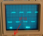
but it looks like sticking to the +ve rail for a period and then it releases and jumps down to the current drive voltage level. That is the time delay until the semi unsaturates?MJL21193 said:I have a clipping "problem" at 20kHz. The sine wave top breaks harshly on the down slope. I don't have a pic of this, but I drew a bit of an illustration below.
Am I right in assuming this is caused by the EF on the VAS going into saturation? If so what is a cure?
Playing with the simulation, if I increase R7 (collector to ground on the EF) from 4.7k to 10k the problem is reduced. What I'd like to know is if this will work in the actual amp and will it have a detrimental effect on the performance.
This shows a little at lower frequency, but is very minor and not as harsh as at 20kHz.
Once the sticking is solved then look at reducing the dropper, 4r7, in the +ve supply rail.
AndrewT said:but it looks like sticking to the +ve rail for a period and then it releases and jumps down to the current drive voltage level. That is the time delay until the semi unsaturates?
Once the sticking is solved then look at reducing the dropper, 4r7, in the +ve supply rail.
Yes, but when I think sticking I think it stays there and doesn't recover. I had that problem before.
I'm going to jumper on the actual amp from the C of Q7 to the C of Q8 and see how that looks.
that's latch up or latching.MJL21193 said:
Yes, but when I think sticking I think it stays there and doesn't recover. I had that problem before.
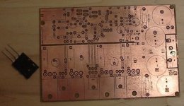
Nice boards John. I especially like the "silk screen". Nice tip from Tom, have to give it a go myself. Haven't seen Tom around here for a while; one of the few who's posts were worth reading.
Anyway, I wonder how well that component overlay transfer would stick to the copper of a double sided board with a top layer ground plane?
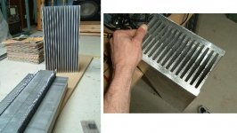
Your heatsink appears to be painted black on the flat side. How do you prepare the aluminium (etch primer?) so that the paint sticks?
I'm comtemplating having a go at painting the heatsink pair for the series pass supply rail regulator of my amp, as they will form the sides of the power supply case. The paint not only has to adhere well, but also be very thin, otherwise it will actually reduce the thermal dissipation of the heatsink.
If it doesn't work out I'll just send them out for black anodising.
Anyway, I'm still waiting for metal work to be done, but I'm afraid I'm going to have to out do you WRT the heatsinks
Pic attached. Series pass regulator heatinks on the left, (to be)fan forced tunnel on the right.
Cheers,
Glen
Anyway, I wonder how well that component overlay transfer would stick to the copper of a double sided board with a top layer ground plane?
Your heatsink appears to be painted black on the flat side. How do you prepare the aluminium (etch primer?) so that the paint sticks?
I'm comtemplating having a go at painting the heatsink pair for the series pass supply rail regulator of my amp, as they will form the sides of the power supply case. The paint not only has to adhere well, but also be very thin, otherwise it will actually reduce the thermal dissipation of the heatsink.
If it doesn't work out I'll just send them out for black anodising.
Anyway, I'm still waiting for metal work to be done, but I'm afraid I'm going to have to out do you WRT the heatsinks
Pic attached. Series pass regulator heatinks on the left, (to be)fan forced tunnel on the right.
Cheers,
Glen
Attachments
MJL21193 said:
I'm going to jumper on the actual amp from the C of Q7 to the C of Q8 and see how that looks.
Ok, doing this, as megajocke suggests, works fine without a load. When a load is connect, it oscillates.
Added the Zobel - still oscillates.
G.Kleinschmidt said:
I wonder how well that component overlay transfer would stick to the copper of a double sided board with a top layer ground plane?
Your heatsink appears to be painted black on the flat side. How do you prepare the aluminium (etch primer?) so that the paint sticks?
but I'm afraid I'm going to have to out do you WRT the heatsinks
Hi Glen. Yeah, I saw though humongous things before (your 70,000 watt class A?? project
)I had to sand this flat with a belt sander, then I used a random orbit sander down to 400 grit. It made it about as smooth as I need (these heatsinks are grossly oversized for the purpose). Cleaned with lacquer thinner and sprayed with ordinary flat black paint in a spray bomb. 2 or 3 thin coats, I can't remember, but enough to give an even appearance.
As for the silkscreen, I have done it on my double sided boards before. It works better on thinner copper (say 1oz as opposed to 2oz) as you tend to lose some print in the "valleys".
Early work. The first real working version of this amp from last year.
Attachments
Attachments

AndrewT said:Hi MJL,
who's toner do you use in the laser printer?
Brother's does not work/transfer/stick and so far I have been unable to source an alternative that fits the Brother HL6050.
Any candidates?
I use an HP Laserjet 3050, with their toner cartridge.
Is a 1N914 a good candidate for a baker clamp?
Is it a realistic concern, this clipping behavior? Should I be spending time trying to fix it, or is it a non-issue for this amp?
MJL21193 said:Is a 1N914 a good candidate for a baker clamp?
Hi John,
Let's say you're clamping only on the positive voltage swing. The cathode of the clamping diode will be at an almost fixed potential, near the positive rail. In the worst case, which is the negative peak of the output voltage, the anode will be almost at the negative rail. So for the breakdown voltage, take the total difference between the positive and negative rails, then add in a safety factor.
It looks like you'll need greater than 100 Volts, maybe 150 Volts minimum. This means the 1N914 at 100V won't cut it. Glen started up a nice thread on this subject here. Keep in mind that some of the high-voltage diodes, such as MUR120/130/140 have a high capacitance, which will increase the high-frequency distortion of the amp. I'm generally not a believer in "magic parts", but this is one component where careful choice can yield real, measurable improvements.
Regarding whether you should address this problem, I won't try to convince you either way, even though I have a definite view on this. For some information regarding the peak-to-average power ratio of music, see this article by Bob Cordell, starting at the bottom left of page 4.
andy_c said:Regarding whether you should address this problem, I won't try to convince you either way, even though I have a definite view on this. For some information regarding the peak-to-average power ratio of music, see this article by Bob Cordell, starting at the bottom left of page 4.
Hi Andy,
Thanks for explaining it. I like to solve every problem, especially if it has a negative impact on sound quality.
I have been mucking around and tried a UF1003 diode. This has neatly fixed the clipping problem (I'll get a picture when my camera battery charges).
Am I wrong in thinking the UF1003 doesn't look bad here? It has high enough reverse voltage and the junction capacitance is reasonably low (20pF).
Now, it was apparent before, but it's more so now that the top is so dead level smooth - I have a similar problem on the bottom, but on a much (much, much) reduced scale. Anything to worry about or is there a simple fix?
I have to say thanks to all those involved here for the excellent advice and pointers I'm getting. The longer this development goes on, the better this amp becomes AND the more informed I become.
I really appreciate the help.
For proof of concept, the UF1003 should be okay. But you can do much, much better for the final circuit. I'm not sure which vendor's datasheet you have for the UF1003, but look at its curve of capacitance vs. reverse voltage and compare it with figure 8 of the BAV21 datasheet. You'll see that near 0 Volts, the capacitance of the BAV21 is about 50 times lower. Also, its variation with voltage is much less - almost negligible really. These combined effects will reduce the distortion due to nonlinear VAS loading and give cleaner recovery from clipping.
I don't know of a simple fix for the negative half cycle, because of the bootstrap.
I don't know of a simple fix for the negative half cycle, because of the bootstrap.
homemodder said:This one would do very nicely 1N6638.
Hi homemodder,
This has very low capacitance...unfortunately it is not available from my main source (Digikey). Thanks.
Andy,
Yes, the BAV21 looks like an excellent choice. Readily available from Digikey. I think this was recommended for a Baker clamp in the original thread for this amp. We went through the same ordeal then. Sometimes I don't learn.
MJL21193 said:
Now, it was apparent before, but it's more so now that the top is so dead level smooth - I have a similar problem on the bottom, but on a much (much, much) reduced scale. Anything to worry about or is there a simple fix?
I'm down to quoting myself.
I knew I had this same situation before, and searched endlessly for it, but here it is. In my mammoth sub amp thread, megajocke again with the pertinent advice;
"The clipping recovery from negative might be a bit strange, it could be bettered by connecting a fast diode with cathode to R40-R41 junction and anode to negative rail. Only needs to cope with the VAS current but it must be able to stand off the rail to rail voltage. This will prevent hard saturation of Q24 during negative clipping."
This is from here.
Now I think of it, this is the reason I have the UF1003's in the first place.

- Status
- This old topic is closed. If you want to reopen this topic, contact a moderator using the "Report Post" button.
- Home
- Amplifiers
- Solid State
- Patchwork Reloaded: Circuit Optimization and Board Layout.