homemodder said:Nice MJL21193
After you have changed to 2sa1381 youll get even better performance. The 2sa1011 are excellent drivers, very good choice.
2sa1360 or 2sa1407 are aslo excellent Vas transistors. Change those 2n devices for something like 2sa970/2sc2240, 2sa992/2sc1845 or 2sa1016/2sc2362 and youll up performance some more.
Hi homemodder,
I don't have any of the 2SA970/C2240, but given the position of the 2N's in my amp - current mirror and cascode - do you think they will make that much of a difference? I think I could use a better device for the EF on the VAS maybe.
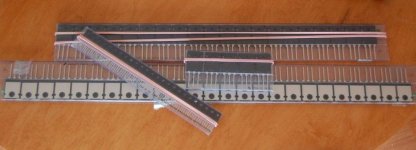
My order came from Digikey. Lots of goodies!
Look at my new outputs and VAS----
Attachments
ferencz said:I simulated your circuit in Microcap-9.
I'm getting ~0.1% THD at 20kHz with 1Vrms input. Mostly first order (40kHz) distortion.
megajocke said:Are you sure the period of the signal, the length of the simulation, the length of the FFT window and all that stuff is setup right?
Try measuring distortion of the input signal to see if it is working right.
Hi ferencz,
Like mega said AND also check idle current. Best results at 50-60mA per device.
Also, as mentioned, models make a huge difference. I have known good models that I'm working with. I have updated quite a few in my library and download from reliable sources (like Fairchild).
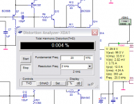
Here's what I have at 20kHz. Input signal 500mV, output power ~14 watts. At full power (145 watts) I get .011%.
Since I can't hear much above ~12kHz anymore, it's not a big deal for me. Still, given the test results from the original amp, these figures are very close to actual, and truly as good as they need to be.
Attachments
Nico Ras said:
I confirm your findings. At 1kHz it is 0.0084%. Also Q3 and Q4 worsens matters slightly and could be omitted.
megajocke said:No, the LPT transistors are 45V types so you can not omit the cascode. One of those things most simulators don't simulate
Nico Ras said:I am sorry 2SC2240 and 2SA970 is 120V so what now?? I thought those where the suggested changes.
Hi Nico,
I'm not going to change the BC550 in the LTP, so the cascode will need to remain. I don't see this as a major source of distortion in the present setup.
The 2N5400 and 2N5550 are not bad for this. Not high fashion, but get the job done.
NOW, the EF might be an area for consideration. Suggestions? Am I correct in my understanding that with 56V rails, this need only be the rail voltage, as it doesn't swing to the negative rail? So maybe a BC556 would look better here?
Thanks for the models homemodder. 
Hi,
I left the input filter and the Zobel, just a quick look at the high frequency stability. When I get the final board layout together for testing, I'll do these runs without the input filter and Zobel.
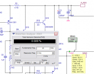
Not correct. I still had the 220pF miller cap (i was experimenting earlier with higher values) in the simulation and a few other things boggled.
More like this. This is at full output power. Fact or fiction, it's what the machine says.
CBS240 said:
Hi
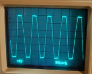
Looking better. Still a little bit slow on the slew for 100KHz, but not bad for this topology.
I usually disconnect the Zobel and input filters during square wave tests. I have burned a Zobel resistor up before with fast signals (crappy little carbon resistor caught fire., now I use metal film).


Hi,
I left the input filter and the Zobel, just a quick look at the high frequency stability. When I get the final board layout together for testing, I'll do these runs without the input filter and Zobel.
MJL21193 said:
Here's what I have at 20kHz. Input signal 500mV, output power ~14 watts. At full power (145 watts) I get .011%.
Not correct. I still had the 220pF miller cap (i was experimenting earlier with higher values) in the simulation and a few other things boggled.
More like this. This is at full output power. Fact or fiction, it's what the machine says.
Attachments
Nico Ras said:
Hard to tell whose models are real, would you consider a manufacturer or an audio enthusiast. By the way these models push the THD up a tad over those supplied by on semi.
Hi Nico,
Andy_c seems to have a competent grip on the simulation process, and I have been using his MJL models since the original amp. These give much better performance than the ones in the Multisim library, or the ones from On Semi.
darkfenriz said:Going below say 0.02% THD at 20kHz in a design like this is hardy doable. I don't know where these 0.0000x% figures came from.
Hi darkfenriz,
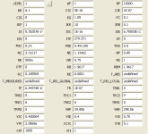
Here the original amp was tested on an HP339A. It pretty much verifies the distortion figures I was getting at the time. All of the changes in the current project have driven the speed up and the distortion down. I'm not looking for ultra-low distortion, but I'll take it if it comes with the effort here.
Hi Nico, good to see some south africans here. Im ex SA.
AndyC s models are excellent in fact, he is much more than just a audio enthusiast. If you look at the graphs vbe/Ic he gets it is much more realistic, it must have taken him a lot of time and patience to get his results. Manufacturers models are terrible especially onsemi, worse ive seen. You got to keep in mind some of these audio enthusiasts are qualified engineers and could easily be working for these companies, if fact some that come to this forum do. If you get worse results with AndyC s models that is what youll get real time, its no use using bad models giving you false indications of better performance if you not gonna get them real life. Have a look at his webpage, he is defenitly qualified to make these models.
MJL21193,
the use of 2sa970 will definetly bring improvement, measured and sonically. The bc s you using arent so bad in ltp, but those 2n devices in current mirror ect are poor performers. Trannies in mirrors and current sources should have very large beta and minimum capacitance, have a look at walt jung s papers. Using 2sa970 in vas Ef will also bring improvement. There is a thread here by fotios in which he wanted to improve rise time of his amp, also a Lin topology. After some failed attempts he tried john curls advice and replaced 2n for the japanese devices, have a look at that thread and improvements he got, he took some pics of his scope too. A simple amp like this can sound very very good if one optimises component choices and working parameters.
Nice devices you got there, does digikey sell 2sa1011 and comp?? What are those output ones?? For these harder to obtain japanese devices you could try bdent, canadian company I think they have large selection and in most cases cheaper than digikey.
Compensation in this topology is critical, I dont understand why you would be increasing the miller instead of reducing it, as long as amp is stable.
homemodder said:
A simple amp like this can sound very very good if one optimises component choices and working parameters.
Nice devices you got there, does digikey sell 2sa1011 and comp?? What are those output ones?? For these harder to obtain japanese devices you could try bdent, canadian company I think they have large selection and in most cases cheaper than digikey.
Compensation in this topology is critical, I dont understand why you would be increasing the miller instead of reducing it, as long as amp is stable.
Hi homemodder,
That is the overall objective - to improve performance, but within reason. I'm picking up bits and pieces as I go through this and become more and more informed. I will run the simulation with higher gain devices and see how the results look. Like I said before, the original amp sounded pretty darn good and measured very well, this had the 2N's in circuit.
I have registered at B&D and found the 970/2240. When I get the chance, I will order some of these excellent looking units.
No, Digikey doesn't sell the 2SA1011, I bought those last year from AmpsLAB.
I did get the 2SB1011 (Panasonic) 2SA914 (Panasonic) and the new ones - 2SA1381 (Fairchild) at Digikey. The outputs are Fairchild 2SC5200/1943. 25 of each.
As for the 220pF for the miller, I was trying a few different things in the simulation, worst case stuff. Just as an exercise, not to implement in the amp. I will be trying lower miller caps as I go along. The present one is 100pF and the amp is dead steady stable.
I changed the outputs and the VAS in the prototype. Stability is awesome. Base stoppers for the outputs are still shorted, so I'll be getting rid of those in the final design / board layout.
I won't show how it looks handling a 100kHz squarewave, because I promised...
But, I do have a clipping pic to share. This is clipping at +/-30V rails, my lab supply maximum.
Attachments
homemodder said:Bad models probably, try these
.MODEL SA1943 PNP (
+ IS =3.5476E-11
+ BF =159.9
+ NF =1.0
+ BR =25.75
+ NR =1.011
+ ISE =2.5119E-10
+ NE =2
+ ISC =7.9433E-11
+ NC =1.37
+ VAF =60.0
+ VAR =11.07
+ IKF =2.8370
+ IKR =0.3548
+ RB =2.74
+ RBM =0.0381
+ IRB =3.6308E-3
+ RE =0.06
+ RC =0.01
+ CJE =4.1783E-9
+ VJE =0.6354
+ MJE =0.3374
+ FC =0.5
+ CJC =1.1383E-9
+ VJC =0.5
+ MJC =0.3699
+ XCJC =0.7624
+ XTB =1.5306
+ EG =1.1751
+ XTI =3.0 )
MODEL 2SC5200 NPN (
+ IS =4.3031E-12
+ BF =152.1
+ NF =1.0
+ BR =6.155
+ NR =1.028
+ ISE =1.3924E-11
+ NE =1.5
+ ISC =2.7542E-11
+ NC =1.95
+ VAF =60.0
+ VAR =6.51
+ IKF =10.8637
+ IKR =0.1585
+ RB =2.47
+ RBM =0.02
+ IRB =0.08
+ RE =0.04
+ RC =0.015
+ CJE =5.8111E-9
+ VJE =0.6506
+ MJE =0.3357
+ FC =0.5
+ CJC =6.4394E-10
+ VJC =0.5
+ MJC =0.3966
+ XCJC =0.7624
+ XTB =1.0445
+ EG =1.1663
+ XTI =3.0 )
Those are different from the ones I have.
The ones I have were downloaded from Fairchild and are excellent models, giving performance equal to or better than andy_c's models.
TRY them
model F5200 NPN
+ IS = 3.0463E-11 BF = 96.20 VAF = 100
+ IKF = 15.04256 ISE = 5.6190E-11 NE = 2.0
+ BR = 4.849 IKR = 1.05012 VAR = 100
+ ISC = 7.18E-8 NC = 1.5 RE = 0.0025
+ RB = 20.18 RBM = 0.0014 IRB = 1.0E-7
+ RC = 0.01137 CJE = 4.5000E-10 CJC = 8.4915E-10
+ VJC = 0.68977 MJC = 0.54081 TF = 6.8583E-10
+ XTF = 9.5721 VTF = 10.425 ITF = 6.8697E-2
+ TR = 1.000E-8 XTB = 1.45 EG = 0.82
+ FC = 0.5
.model F1943 PNP
+ IS=1.30E-10 BF=91.42 VAF=100
+ IKF=4.480 ISE=1.02E-10 NE=2.0
+ VAR=100 ISC=5.0900E-9 NC=1.5
+ BR=0.882 IKR=2.9015 RE=0.0011
+ RC=0.0553 RB=140.05 RBM=0.0041
+ IRB=8.5e-9 CJE=2.00E-10 FC=0.5
+ CJC=9.45E-10 VJC=0.48 MJC=0.28
+ TF=9.250E-10 XTF=10 VTF=10
+ ITF=1 TR=1.00E-8 EG=0.76
+ XTB=2.68
homemodder said:Hi Nico, good to see some south africans here. Im ex SA.
Hi homemodder, I would agree with you that some engineers might be working at semi-conductor manufacturers.
If these engineers do not correct their company's errors they are unworthy of an engineering position and should be fired.
If you claim that On-Semi (ex Motorola) gives inaccurate specifications for their products that may be used in life support systems, aerospace, etc. how do you explain that they still exists.
Accurate specifications are not only for DIY audio enthusiasts but is far more important to the engineer designing critical equipment to sustain life.
Just imagine if you had to be attached to a hart lung machine that uses On-Semi components, what is the probability of your survival.
Regards from S.A.
Nico you have a valid point, but you must keep in mind spice is far from perfect. Its a simulation program, a guide you may call it. Aeronotic pilots are nowadays also taught on simulators but ask anyway of them, its far from flying a real aeroplane. The simulator cannot forsee a sudden hot air packet and even less its complicated effects.
Specifications given on datasheets is a very different matter, here I dont doubt the products will be very close to those specs. Another thing about the models is that a competing company could produce similar components if so much info was given on a specific spice model. Have a look at what info a model can give about a component. Ill give you specs of a amp but I will not reveal whats inside type of thing.
Scott Wurcer has said in the blowtorch thread that analog devices does models which they use to design opamps. These models are not available to others but he says they are very very accurate. Now if you were to use the models of their opamps you will very quickly realise they deviate some from specs.
AndyC saw discrepancies with the onsemi models and improved them to better match the datasheets.
One quick look at the last the last models that MJL21193 put up, and ll tell you straight away they are offspec. For one I doubt a power transistor like 2sa1943 can have a early voltage as high as 100 and its less likely that it will math the voltage of the npn counter part. What is useful with a model in a design is that you can play around with certain parameters to see what effect it has on a design, like decreasing cob on a model and verifying its impact on say a vas. Again its only a guide on how certain parameters are going to influence the design.
MJL21193, thats strange my models also come from fairchild, why are they different.
MJL21193 said:
I have registered at B&D and found the 970/2240. When I get the chance, I will order some of these excellent looking units.
Pacific Semiconductor in Vancouver have these parts, as well as the 992/1845 pair at good prices. I've bought there before and they seem fine to deal with over the internet. If you want to try any of these out first I can send you some.
Steve.
homemodder said:Nico you have a valid point, but you must keep in mind spice is far from perfect. ....
Hi homemodder, I know what you are saying, I have been using MicroCAP when it first appeared on the market in the early 90's and every upgrade since for quickly "paper testing" a design, then divert to good old Hewlett Packard for confirming design performance to the engineering specification.
I must admit that I (nor any of my engineers) need major changes as this package offer a lot of tools to help the experienced engineer in predicting a very stable outcome in a relatively short time and that is the purpose of such a package, no more and no less.
Believe me I get suspicious when simulators predict performances that one knows from experience are impossible to achieve, even under perfect conditions.
I applaud what John is doing here because he oscillates between simulation and actually and each time he makes a change he then verifies the outcome practically.
John you do not bore me with any of your analysis, good work. You will be pleased with the final result because you follow good engineering principles.
Kind regards
Nico
homemodder said:MJL21193, thats strange my models also come from fairchild, why are they different. [/B]
Just a final note, no two manufacturers make identical parts. That is why an engineer will specify a particular manufacturer for a particular part.
If AndyC has optimized the On-Semi part let me assure you that it will not be optimized for another manufacturer.
Anyone assuming that a BC550 from Philips is the same as a BC550 from another manufacturer lack experience.
Nico
homemodder said:
One quick look at the last the last models that MJL21193 put up, and ll tell you straight away they are offspec. For one I doubt a power transistor like 2sa1943 can have a early voltage as high as 100 and its less likely that it will math the voltage of the npn counter part. What is useful with a model in a design is that you can play around with certain parameters to see what effect it has on a design, like decreasing cob on a model and verifying its impact on say a vas. Again its only a guide on how certain parameters are going to influence the design.
MJL21193, thats strange my models also come from fairchild, why are they different.
Hi homemodder,
I don't know why they would be different, the models come from here.
I believe these are good because when used in their dedicated purpose (outputs) they don't increase distortion in the simulation, over using the MJL models from andy_c. In fact, distortion goes down slightly with these models. My logic is that the device, if well matched to the purpose, should not be a source of significant distortion, therefore lower is more accurate. Am I wrong in this assessment?
Changing VAF and VAR to another value seems to have a negligible effect on the simulation performance for this type of device anyway.
spind said:
Pacific Semiconductor in Vancouver have these parts, as well as the 992/1845 pair at good prices. I've bought there before and they seem fine to deal with over the internet. If you want to try any of these out first I can send you some.
Steve.
Thanks Steve,
You are very generous.
I will go ahead and order some of these from Pacific, as they are very highly regarded devices. I see they are in the voltage that I most often play, so they will undoubtedly come in handy.
Nico Ras said:
I applaud what John is doing here because he oscillates between simulation and actually and each time he makes a change he then verifies the outcome practically.
John you do not bore me with any of your analysis, good work. You will be pleased with the final result because you follow good engineering principles.
Thanks Nico,
It's nice to be in this position - to be able to simultaneously simulate and test on the actual circuit. I don't know enough yet to say one way or the other whether something will work as simulated, therefore I learn quite a bit as I go through.
This amp is comprised of bits and pieces of other designs, with it all thrown together and "optimized" by simulation. So far, I think the results have been good and proves the value of simulation as a fairly accurate design tool and a means to expedite learning.
I would not have the limited understanding I have today without it's help.
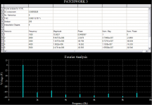
I have done an experiment. I have taken a few very popular designs and modeled them using the same device models as the Patchwork uses. In all cases this means the lowest possible distortion figure. I have set the bias current to the appropriate amount and used the same input for each (500mVAC signal at 20kHz). This is distortion at 20kHz.
First the design on this thread - Patchwork:

Next is the venerable Krell50:

SYMASYM:

And finally ESP project 3A:

Hi John,
I am not familiar with your simulator, but I am afraid that you are not comparing apples to apples in the different simulations. You should compare these amps all at the same output level as distortion increases at twice the rate of the power increase and this has to do with the theoretical third order compression.
If I look at the Y-axis it appears to be in dB referenced to the fundamental because a quick calculation between the magnitude of the fundamental and the first harmonic it is approx 20 log V2/V1 = -105 dB
I also assume that the fundamental in your amp's simulation has a peak to peak amplitude of 15V which would be approximately 3.5 watt into 8 ohms (provided of course that it was loaded by 8 ohms in the simulation).
THD is the accumulated power of all harmonics to that in the fundamental and I normally take up to the ninth harmonic to get what I believe is an accurate reflection of the THD, which is appropriate especially when analyzing the lower frequencies. (Your amplifier is capable of producing meaningful output far above 200 kHz.)
I am not sure what the meaning of the DC component is and I take it this is the offset at the amplifier output because there should be zero DC component in an AC signal. DC components are usually due to either off-set, clipping or that the output swings more in one direction than the other.
Kind regards
Nico
Nico Ras said:Hi John,
I am not familiar with your simulator, but I am afraid that you are not comparing apples to apples in the different simulations. You should compare these amps all at the same output level as distortion increases at twice the rate of the power increase and this has to do with the theoretical third order compression.
Hi Nico,
There is some validity to my tests, even though I picked a fixed input signal which has each amp outputing different amounts of power.
I re-did the tests, making the output power approximately equal in all four (15 watts into 8 ohms). The results were not much different. Tests at 20kHz, 3 harmonics.
Patchwork: .00272%
ESP 3A: .03627%
Krell 50: .00281%
SYMASYM: .00769%
Tests at the same power output at 1kHz, 9 harmonics.
Patchwork: .000112%
ESP 3A: .014476%
Krell 50: .001407%
SYMASYM: .003651%
Attachments
Hi MJL21193
You Guys in canada are spoilt for components I see, even pacific have some very good parts, and there is another distributor I cannot recall now that has virtually every single audio japanese transistor made.
The manufacturers can drive us crazy with all the models, the ones I have are the KSA1943 and KSC5200, the datasheets are the same, now how does this figure???? Anyway its not much use using the models which will show best results in simulators if that is not going to be the case real life. Rather have higher distortion figures but accurate.
What is very useful of those sims is the spectrum, and you have showed some amps which are very good sounding. When you look youll see the the uneven harmonics are less than even and there is some associated to what youll hear subjectively to a certain degree. Your sims are actually very close to real measurements in this respect. Your case looks good although you have 3rds up on the second harmonic. No train smash here, what you need to worry about is 7th and up, they turn things nasty. In your case your amp should sound just a tad more bright but a lot of people prefer it that way anyway. I suspect its the cascodes doing, reason I dont like them much and rather use excellent measuring trannies to reduce the problem of capacitance, although you have to use it because of the voltage of the bc parts. In your sims try using 2sa970 models but without the cascodes and look at the spectrum you get. Irrespective I would recommend you to use 2sa1016/comp or 2sa992/comp seeing that pacific and bd have them and their is not much price difference. These have less than half the cap of 2sa970, ive used them for nearly 17 years and find them subjectively superior to 2sa970. Would save you some parts and complexity too.
How are the listening tests going??
- Status
- This old topic is closed. If you want to reopen this topic, contact a moderator using the "Report Post" button.
- Home
- Amplifiers
- Solid State
- Patchwork Reloaded: Circuit Optimization and Board Layout.