Nico Ras said:Hi John,
Experiment with a 100 - 470 uF cap between the emitters of Q1 and Q2 and have a look see what it does with your already minuscule distortion. The results may be interesting in future designs.
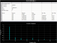
And the simulation says....
This is with a 470uF cap across the emitters of the LTP.
Attachments
megajocke said:
Though, if you take an optimized design which was designed around an LTP with emitter resistors it will increase the open loop gain bandwith product possibly making the amplifier unstable.
Worth trying in the prototype to check for stability?
megajocke said:
Then you will have good margin with 2 pairs. That is a pretty stiff supply, looks nice too")
Thank you sir!
The power supplies have been built for a couple months now. I thought I'd make sure I have those done before the amps and I wouldn't be tempted to rig up a temporary one to short out and explode.
I'm going to go ahead and order the Fairchild 2SC5200/1943 for these. Even though I have many MJL's, I have many projects in my future - these will keep.
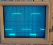
Here's the above square wave magnified. This is through the input stage LP filter, BTW.
Attachments
megajocke said:
If you design around it I guess you could make it work in an excellent way. In a symmetric circuit with two LTP:s (one per rail) it would be useful as it lets you use large emitter resistors for good DC balance in the input stage.
MJL21193 said:
And the simulation says....
This is with a 470uF cap across the emitters of the LTP.
Well, in real life it does destabilize the amp as megajocke said . Oh well, one for that future symmetrical project...
Did some more squarewave testing:


Boring, I know...
Performance is very good now and I'll do a schematic update soon.
MJL21193 said:
And 500kHz
A mistake on my part - that was more like 250kHz. Oh well.
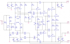
Schematic update. I have ordered the 2SC5200/1943 for the outputs. I have changed the drivers to the 2Sc2344/2SA1011 combo.
I have changed the Vbe multiplier to a BD139 and changed the VAS to 2SA1381. A couple of other minor changes and that's it (for now).
Attachments
For base stoppers I searched for 1/4 watt 2 ohm resistors on Digikey, but the minimum is something like 10 million, so I'm SOL.
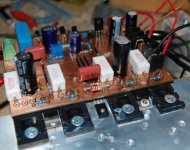
Looking at the pic below of the (latest) prototype, I've shorted the base stoppers without a problem - very stable. I'll need to check again with the new outputs to see if it has the same stability.
In the pic is my third board layout for this amp. I have a newer one that is much better but I haven't etched it yet. I thought I would work the bugs out on this board, then I'd could go straight to making 6 of the new ones.
Along with the new outputs, I ordered some 2SA1381 for the VAS. In the prototype below. This is the "F" - hfe=160. I had a 2SA1011 in that position but changed it out for a 2SB1011 to test (I used the 2SA1011 for a driver - recycle).
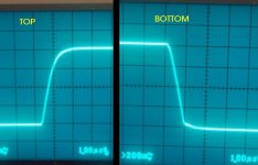
With the new temporary VAS, the drivers changed and the Vbe change, there is a notable difference in the performance, at least visually on the scope. Very stable, flat square waves (I'll show later) up to 100kHz, still look like square waves at 200kHz.
Clipping is very clean, much more so now than before where the top half would "quiver".
What can I attribute the improvement too? The new drivers? Most likely. The 2SB1011 is none to shabby for the VAS either, I used it on another project with good success.
I'm looking forward to chance to have listen, maybe as early as this weekend.
Looking at the pic below of the (latest) prototype, I've shorted the base stoppers without a problem - very stable. I'll need to check again with the new outputs to see if it has the same stability.
In the pic is my third board layout for this amp. I have a newer one that is much better but I haven't etched it yet. I thought I would work the bugs out on this board, then I'd could go straight to making 6 of the new ones.
Along with the new outputs, I ordered some 2SA1381 for the VAS. In the prototype below. This is the "F" - hfe=160. I had a 2SA1011 in that position but changed it out for a 2SB1011 to test (I used the 2SA1011 for a driver - recycle).
With the new temporary VAS, the drivers changed and the Vbe change, there is a notable difference in the performance, at least visually on the scope. Very stable, flat square waves (I'll show later) up to 100kHz, still look like square waves at 200kHz.
Clipping is very clean, much more so now than before where the top half would "quiver".
What can I attribute the improvement too? The new drivers? Most likely. The 2SB1011 is none to shabby for the VAS either, I used it on another project with good success.
I'm looking forward to chance to have listen, maybe as early as this weekend.
Attachments
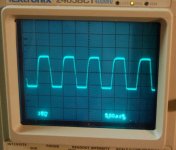
I swear this is the last squarewave...
100kHz at about 5 watts (sine wave power output). Zobel resistor was getting pretty hot during these tests, done with +/-30 volts from my regulated supply.
The original version of this amp could not do this. Yeah, this and $1.50 will get you a coffee.
100kHz at about 5 watts (sine wave power output). Zobel resistor was getting pretty hot during these tests, done with +/-30 volts from my regulated supply.
The original version of this amp could not do this. Yeah, this and $1.50 will get you a coffee.
Attachments

Nice MJL21193
After you have changed to 2sa1381 youll get even better performance. The 2sa1011 are excellent drivers, very good choice.
2sa1360 or 2sa1407 are aslo excellent Vas transistors. Change those 2n devices for something like 2sa970/2sc2240, 2sa992/2sc1845 or 2sa1016/2sc2362 and youll up performance some more.
Attribute the improvement from the vas in your case, youve made a huge upgrade to your vas by using 2sb1011. Just compare the cob for instance.
Since you need less capacitance to swamp the nonlinear capacitance accross the vas transistor, you could lower the vas cap too. Mainly sonic improvement.
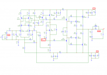
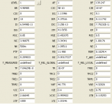
ferencz said:I simulated your circuit in Microcap-9.
I'm getting ~0.1% THD at 20kHz with 1Vrms input. Mostly first order (40kHz) distortion.
Any ideas?
PS.: Sry for low-quality schematic
I confirm your findings. At 1kHz it is 0.0084%. Also Q3 and Q4 worsens matters slightly and could be omitted.
Bad models probably, try these
.MODEL SA1943 PNP (
+ IS =3.5476E-11
+ BF =159.9
+ NF =1.0
+ BR =25.75
+ NR =1.011
+ ISE =2.5119E-10
+ NE =2
+ ISC =7.9433E-11
+ NC =1.37
+ VAF =60.0
+ VAR =11.07
+ IKF =2.8370
+ IKR =0.3548
+ RB =2.74
+ RBM =0.0381
+ IRB =3.6308E-3
+ RE =0.06
+ RC =0.01
+ CJE =4.1783E-9
+ VJE =0.6354
+ MJE =0.3374
+ FC =0.5
+ CJC =1.1383E-9
+ VJC =0.5
+ MJC =0.3699
+ XCJC =0.7624
+ XTB =1.5306
+ EG =1.1751
+ XTI =3.0 )
MODEL 2SC5200 NPN (
+ IS =4.3031E-12
+ BF =152.1
+ NF =1.0
+ BR =6.155
+ NR =1.028
+ ISE =1.3924E-11
+ NE =1.5
+ ISC =2.7542E-11
+ NC =1.95
+ VAF =60.0
+ VAR =6.51
+ IKF =10.8637
+ IKR =0.1585
+ RB =2.47
+ RBM =0.02
+ IRB =0.08
+ RE =0.04
+ RC =0.015
+ CJE =5.8111E-9
+ VJE =0.6506
+ MJE =0.3357
+ FC =0.5
+ CJC =6.4394E-10
+ VJC =0.5
+ MJC =0.3966
+ XCJC =0.7624
+ XTB =1.0445
+ EG =1.1663
+ XTI =3.0 )
Or even better these, modified and improved by andyC
.MODEL mjl3281a_x npn IS=9.8145e-12 BF=438.0 NF=1.00 VAF=38 IKF=19.0 ISE=1.0e-12 NE=1.1237388682 BR=4.98985 NR=1.09511 VAR=4.32026 IKR=4.37516 ISC=3.25e-13 NC=3.96875 RB=3.997 RE=0.00 RC=0.06 XTB=0.115253 XTI=1.03146 EG=1.11986 CJE=1.144e-08 VJE=0.468574 MJE=0.34957 TF=2.6769e-9 XTF=7500 VTF=3.0 ITF=1000 CJC=1.093685e-9 VJC=0.623643 MJC=0.482111 XCJC=0.959922 FC=0.1 CJS=0 VJS=0.75 MJS=0.5 TR=1e-07 PTF=0 KF=0 AF=1 Vceo=200 Icrating=15
.MODEL mjl1302a_x pnp IS=9.8145e-12 BF=122.925 NF=1.00 VAF=40 IKF=19 ISE=9.18577762370362E-07 NE=5.0 BR=4.98985 NR=1.09511 VAR=4.32026 IKR=4.37516 ISC=3.25e-13 NC=3.96875 RB=3.30 RE=0.00 RC=0.06 XTB=0.115253 XTI=1.03146 EG=1.11986 CJE=1.561e-08 VJE=0.781803 MJE=0.433868 TF=3.257e-9 XTF=1000 VTF=2.0 ITF=260 CJC=2.346838e-9 VJC=0.27876 MJC=0.411324 XCJC=0.959922 FC=0.1 CJS=0 VJS=0.75 MJS=0.5 TR=1e-07 PTF=0 KF=0 AF=1 Vceo=200 Icrating=15
MJL21193 said:I swear this is the last squarewave...
100kHz at about 5 watts (sine wave power output). Zobel resistor was getting pretty hot during these tests, done with +/-30 volts from my regulated supply.
The original version of this amp could not do this. Yeah, this and $1.50 will get you a coffee.
Hi
Looking better. Still a little bit slow on the slew for 100KHz, but not bad for this topology.
I usually disconnect the Zobel and input filters during square wave tests. I have burned a Zobel resistor up before with fast signals (crappy little carbon resistor caught fire.

 , now I use metal film).
Attachments
megajocke said:No, the LPT transistors are 45V types so you can not omit the cascode. One of those things most simulators don't simulate
I am sorry 2SC2240 and 2SA970 is 120V so what now?? I thought those where the suggested changes.
homemodder said:Or even better these, modified and improved by andyC
.MODEL mjl3281a_x npn IS=9.8145e-12 BF=438.0 NF=1.00 VAF=38 IKF=19.0 ISE=1.0e-12 NE=1.1237388682 BR=4.98985 NR=1.09511 VAR=4.32026 IKR=4.37516 ISC=3.25e-13 NC=3.96875 RB=3.997 RE=0.00 RC=0.06 XTB=0.115253 XTI=1.03146 EG=1.11986 CJE=1.144e-08 VJE=0.468574 MJE=0.34957 TF=2.6769e-9 XTF=7500 VTF=3.0 ITF=1000 CJC=1.093685e-9 VJC=0.623643 MJC=0.482111 XCJC=0.959922 FC=0.1 CJS=0 VJS=0.75 MJS=0.5 TR=1e-07 PTF=0 KF=0 AF=1 Vceo=200 Icrating=15
.MODEL mjl1302a_x pnp IS=9.8145e-12 BF=122.925 NF=1.00 VAF=40 IKF=19 ISE=9.18577762370362E-07 NE=5.0 BR=4.98985 NR=1.09511 VAR=4.32026 IKR=4.37516 ISC=3.25e-13 NC=3.96875 RB=3.30 RE=0.00 RC=0.06 XTB=0.115253 XTI=1.03146 EG=1.11986 CJE=1.561e-08 VJE=0.781803 MJE=0.433868 TF=3.257e-9 XTF=1000 VTF=2.0 ITF=260 CJC=2.346838e-9 VJC=0.27876 MJC=0.411324 XCJC=0.959922 FC=0.1 CJS=0 VJS=0.75 MJS=0.5 TR=1e-07 PTF=0 KF=0 AF=1 Vceo=200 Icrating=15
Hard to tell whose models are real, would you consider a manufacturer or an audio enthusiast. By the way these models push the THD up a tad over those supplied by on semi.
- Status
- This old topic is closed. If you want to reopen this topic, contact a moderator using the "Report Post" button.
- Home
- Amplifiers
- Solid State
- Patchwork Reloaded: Circuit Optimization and Board Layout.