The hybrid CFP driver of the Quad triple looks interesting - only two B-E junctions to temperature compensate.
I doubdt the HF crossover distortion performance is ideal though.
I'm currently experimenting with this as the series pass element in my 100A peak power supply.
Cheers,
Glen
I doubdt the HF crossover distortion performance is ideal though.
I'm currently experimenting with this as the series pass element in my 100A peak power supply.
Cheers,
Glen
Attachments
I put a 1k in series with R21. This allowed me to adjust the idle current to decent number for the +/-30 supply.
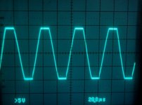
Looking at clipping performance and I see that this clamp did not completely cure the slight sticking in the bottom half. Decreased yes, but not eliminated.
Clipping is very symmetrical - top and bottom start to clip at the same time.
Looking at clipping performance and I see that this clamp did not completely cure the slight sticking in the bottom half. Decreased yes, but not eliminated.
Clipping is very symmetrical - top and bottom start to clip at the same time.
Attachments
MJL21193 said:
I'll answer my own question: Vbe multiplier was thrown off by this clamp arrangement. It was drawing current too over bias the outputs. I adjusted the Vbe pot and brought it back down to normal.
I'm going to bring the voltage up to +/-30V...
...It won't go there. The Vbe resistor values will need to be changed as I can't adjust the pot low enough.
Hi John. One of the most obvious and greatest drawbacks of the bootstrapped VAS (which I did not think of ‘till now) is the fact that the quiescent VAS current is proportional to the supply voltage.
The problem here is that the VBE multiplier has a small dynamic resistance, so the reasonably critical biasing voltage for the output stage will vary along with the rail voltage.
If you set the output stage quiescent current with a reduced rail voltage (say +/-15V) you’ll find that it will increase when you crank the variac up for the full rail voltage.
Cheers,
Glen
That might be about as good as you will get it.Decreased yes, but not eliminated.
The DX amp (more simple [edit]
bootstrap amp than yours)"sticks" much more than yours
when overdriven with music into a loudspeaker. So you have reached bootstrap nirvana.(I just built it and used it ,...before reading your thread)
With a dynamic load (full range speaker) VAS loading
and Vbias [D. self]will fluctuate greatly. A few solutions to this:
1.Higher gain drivers (no added components)
2.Triple output configuration (2 more components)
3.Higher current VAS (bigger bootstrap)
4.Current source (slightly higher distortion with signal gen
and spice but with a real speaker most likely less.
1 AND 3 might be best for patchwork..

I really don't have it in for this amp topology (little DX amp's
are in my bedroom,they are reliable and sound warm)
but without active current sourcing a whole new "can of worms"
is opened.I've seen some big names like Marantz and pioneer
use your techniqes in midrange equiptment but at the
top end they go active source.
G.Kleinschmidt said:
Hi John. One of the most obvious and greatest drawbacks of the bootstrapped VAS (which I did not think of ‘till now) is the fact that the quiescent VAS current is proportional to the supply voltage.
The problem here is that the VBE multiplier has a small dynamic resistance, so the reasonably critical biasing voltage for the output stage will vary along with the rail voltage.
If you set the output stage quiescent current with a reduced rail voltage (say +/-15V) you’ll find that it will increase when you crank the variac up for the full rail voltage.
Cheers,
Glen
Here is a quick simulation to demonstrate the problem.
A Vbe multiplier is made and the 10mA standing current is modulated +/-10%.
This results in a voltage variation of ~50mVpp.
With 0.27ohm emitter balast resistors this would result in a output stage bias variation of nearly 100mA.
Cheers,
Glen
Attachments
G.Kleinschmidt said:
Hi John. One of the most obvious and greatest drawbacks of the bootstrapped VAS (which I did not think of ‘till now) is the fact that the quiescent VAS current is proportional to the supply voltage.
High Glen,
It was covered by Andrew earlier and of course well know be me as I have to readjust the idle current for new operating voltages. This is a problem during testing at different (lower) voltages only and doesn't pose a problem during full power usage of the amp.
ostripper said:
That might be about as good as you will get it.
The DX amp (more simple [edit]
bootstrap amp than yours)"sticks" much more than yours
when overdriven with music into a loudspeaker. So you have reached bootstrap nirvana.(I just built it and used it ,...before reading your thread)
With a dynamic load (full range speaker) VAS loading
and Vbias [D. self]will fluctuate greatly. A few solutions to this:
1.Higher gain drivers (no added components)
2.Triple output configuration (2 more components)
3.Higher current VAS (bigger bootstrap)
4.Current source (slightly higher distortion with signal gen
and spice but with a real speaker most likely less.
1 AND 3 might be best for patchwork..
I really don't have it in for this amp topology (little DX amp's
are in my bedroom,they are reliable and sound warm)
but without active current sourcing a whole new "can of worms"
is opened.I've seen some big names like Marantz and pioneer
use your techniqes in midrange equiptment but at the
top end they go active source.
Hi OS,
First off, a question: Which did you build - the DX or this amp?
With all due respect to Carlos, this isn't the DX. Far from it actually. The only similarity really is the use of bootstrap current source.
While I don't have the technical understanding to argue it, I think there quite a bit of hot air in the suggestion that bias will fluctuate greatly when driving a speaker, and this phenomenon is limited to the bootstrap current source. I have measured the DC bias at the base of the drivers while the original amp was playing music into a speaker and I didn't see this happening.
The very tip-top high end amps can have the active current source.
This low-end shop effort will stick with the bootstrap.
G.Kleinschmidt said:Here is one possible solution to the VBE multiplier bias problem.
A VBE multiplier is made with a NPN-PNP compound pair.
Under the same testing conditions (10mA+/-10%) the pp bias voltage variation is reduced from ~50mV to 4mV.
This is fine Glen, but is it necessary? With my proper permanent supply, I was experiencing rock steady idle current.
TBH I'd rather go with the active current source, rather than accommodate another TO-126 on the heatsink.
megajocke said:R29 must connect to other side of D3 for it to work correctly. D3 is for reducing the available voltage as D2 will clamp outside rail voltage.
The way it's connected now D3 increases bias instead.
See, when I "talk" to you, I get the impression that all of this is second nature to you. The mark of a professional.
Yes, you are dead on as usual. Moving the driver base stopper to the Vbe side of the 1N4148 brought everything back to the way it was before. Thanks.

Unfortunately, duty calls, and I need to go out and earn some money today, then come back and try to catch up on the office work I've been neglecting while I've been fooling around with this.
I'll be back with the results from more changes soon...
andy_c said:
Yeah, at these sub-ppm distortion levels at low frequency, the cap distortion could very well dominate. I don't know how to model capacitor distortion in SPICE. I bought the Cyril Bateman CD, so I'm familiar with the nice work he did. I know he found that non-polar electrolytics have lower distortion than their polar counterparts. Might be something to consider. Mouser has the Nichicon non-polars for good prices.
Edit: Here's Cyril Bateman's web site:
http://uk.geocities.com/cyrilb2@btinternet.com/
Yes I've downloaded most of Cyril's papers and have been thinking myself that I'd use NPE's when large values are required other than in the power supply. Happened to notice these 3% DF types, not that DF is an issue in high impedance circuits:
http://www.erse.cc/caps/npe/npe.asp?reset=1
Pete B.
No,MJL , I built the DX. But your thread sparked my interest
in why a bootstrap sounds different. (I scoped my DX's)
Looking at your filter caps, I don't think you have anywhere
as much ripple as some , so loading and bias fluctuations
might not be as evident. With 6800-10k uf per rail one
might see (even hear) PSRR artifacts under load.
Don't be hard on your design, calling it a "low-end shop design",
to the contrary ,30% of my 200+ commercial amp schematics
show some form of bootstrapping.(I read them all)
I've built small amps for everyone else in the house, now I want
one for me. CCS,balanced VAS's, bootstrap.. too many choices
 I don't have the money to burn , so I have to
get it right the first time.
in why a bootstrap sounds different. (I scoped my DX's)
Looking at your filter caps, I don't think you have anywhere
as much ripple as some , so loading and bias fluctuations
might not be as evident. With 6800-10k uf per rail one
might see (even hear) PSRR artifacts under load.
Don't be hard on your design, calling it a "low-end shop design",
to the contrary ,30% of my 200+ commercial amp schematics
show some form of bootstrapping.(I read them all)
I've built small amps for everyone else in the house, now I want
one for me. CCS,balanced VAS's, bootstrap.. too many choices
I don't have the money to burn , so I have toget it right the first time.
The effect of mains voltage variations approaching +-10% should be examined in all parts of the circuit, not just the LTP & VAS.
D.Self's collector resistor (8r1 to 18r) will provide a bit of correction for variable VAS current and retain the simplicity of the single transistor multiplier.
I wonder what will happen when the Input LTP mirror is deleted and replaced with ordinary resistor loading?
D.Self's collector resistor (8r1 to 18r) will provide a bit of correction for variable VAS current and retain the simplicity of the single transistor multiplier.
I wonder what will happen when the Input LTP mirror is deleted and replaced with ordinary resistor loading?
Thank you ,andrew..
R23 is the one, right?

I always wondered what that resistor was compensating for.D.Self's collector resistor (8r1 to 18r)
R23 is the one, right?
Yes R23 in that diagram moves the VAS current vs Vbe multiplier voltage around.
The flat top of the curve can be moved to the general area of normal VAS current and then small variations move the the multiplier voltage downwards but initially only slightly.
Without R23 the curve is steeply sloping and the slope is ~50times worse than when R23 is correctly selected.
The flat top of the curve can be moved to the general area of normal VAS current and then small variations move the the multiplier voltage downwards but initially only slightly.
Without R23 the curve is steeply sloping and the slope is ~50times worse than when R23 is correctly selected.
That resistor might be good for the patchwork and my xmas amp.
most of self's amps use 22R, i'll just play around with it.
1. DC offset
2.crappy PSRR
3.more distortion
that is why blameless amps sound better (different)
than ampslab c200 (built that-it works but even the
designer claims it sounds "strained" at times)
most of self's amps use 22R, i'll just play around with it.
by andrew T. I wonder what will happen when the Input LTP mirror is deleted and replaced with ordinary resistor loading?
1. DC offset
2.crappy PSRR
3.more distortion
that is why blameless amps sound better (different)
than ampslab c200 (built that-it works but even the
designer claims it sounds "strained" at times)
ostripper said:No,MJL , I built the DX. But your thread sparked my interest
in why a bootstrap sounds different. (I scoped my DX's)
Ah.
ostripper said:
Looking at your filter caps, I don't think you have anywhere
as much ripple as some , so loading and bias fluctuations
might not be as evident. With 6800-10k uf per rail one
might see (even hear) PSRR artifacts under load.
Well, I have no ripple worth mentioning, along with that there isn't any noise from the amp at idle - nothing. When I said this earlier (about my son taking a listen) I wasn't exaggerating.
The much talked about turn on thump that plagues resistive load front ends and bootstrap amps is not there either. Application of +/-56VDC and the speaker cone noiselessly, slowly moves in and out by about a mm. It's beautiful really.
ostripper said:
Don't be hard on your design, calling it a "low-end shop design",
to the contrary ,30% of my 200+ commercial amp schematics
show some form of bootstrapping.(I read them all)
That was me playing at modesty...
ostripper said:
I've built small amps for everyone else in the house, now I want
one for me. CCS,balanced VAS's, bootstrap.. too many choices
get it right the first time.
Stay tuned and when we are through here, build this one.
AndrewT said:The effect of mains voltage variations approaching +-10% should be examined in all parts of the circuit, not just the LTP & VAS.
D.Self's collector resistor (8r1 to 18r) will provide a bit of correction for variable VAS current and retain the simplicity of the single transistor multiplier.
Hi Andrew,
I did examine all the effects, back 50 or 60 posts ago. The effect on this amp with a good power supply will be negligible.
I included that resistor in the original patchwork, but missed it here. I will put it back in.
AndrewT said:
I wonder what will happen when the Input LTP mirror is deleted and replaced with ordinary resistor loading?
It becomes a Symasym, or a 3A, or some other amp.
PB2 said:Cyril's papers
JC seems to hold the view that the name should be Patrick Bateman, not Cyril.
Very entertaining thread, John the doorstep heatsinker.
more changes...
Thing 2: I moved the bootstrap caps feed from the output to the emitter of the lower driver. In the simulation, this brings on a massive drop in distortion.
In the actual amp, there is little to observe. I have the same rock solid stability as before, clipping behavior is unchanged. All systems are go for -
Thing 3: Increase the emitter resistors on the diff pair and drop the Miller cap value. Using Andy's formula (thanks again ), I considered how far I should go. I thought I'd consider the capacitance of the clamp diode I'm using (20pF) and therefore I used 2 - 15pF's in parallel. I replaced R23 and 24 with 75ohm.
With my 30V lab supply stability is still good, though there is some overshoot on the leading edge of the squarewave. Clipping looks fine at 20kHz.
I screwed it back onto the heatsink and tried it at full power. It looks really good. The overshoot on the squarewave is gone and clipping still looks good. Clipping at full rail voltage was before and still isn't as clean as at the lower supply voltage. There is a tiny touch of that sticking that shows in the bottom wave in the top too, but it's well into clipping when it happens and it doesn't show signs of instability.
So, all three changes executed successfully. I will work up a revised schematic with these changes.
Thing 2: I moved the bootstrap caps feed from the output to the emitter of the lower driver. In the simulation, this brings on a massive drop in distortion.
In the actual amp, there is little to observe. I have the same rock solid stability as before, clipping behavior is unchanged. All systems are go for -
Thing 3: Increase the emitter resistors on the diff pair and drop the Miller cap value. Using Andy's formula (thanks again
), I considered how far I should go. I thought I'd consider the capacitance of the clamp diode I'm using (20pF) and therefore I used 2 - 15pF's in parallel. I replaced R23 and 24 with 75ohm.With my 30V lab supply stability is still good, though there is some overshoot on the leading edge of the squarewave. Clipping looks fine at 20kHz.
I screwed it back onto the heatsink and tried it at full power. It looks really good. The overshoot on the squarewave is gone and clipping still looks good. Clipping at full rail voltage was before and still isn't as clean as at the lower supply voltage. There is a tiny touch of that sticking that shows in the bottom wave in the top too, but it's well into clipping when it happens and it doesn't show signs of instability.
So, all three changes executed successfully. I will work up a revised schematic with these changes.
jacco vermeulen said:
JC seems to hold the view that the name should be Patrick Bateman, not Cyril.
Very entertaining thread, John the doorstep heatsinker.
Hey jacco,
Thanks, I try to reduce, reuse, recycle whenever possible...just doing my part for the environment.
Along the way I create a ship-load of work for myself and save a few pennies.
Patrick Bateman, one of my favourite investment bankers, probably doesn't know a lot about capacitors. Mergers and acquisitions at Pierce & Pierce if I'm not mistaken.
- Status
- This old topic is closed. If you want to reopen this topic, contact a moderator using the "Report Post" button.
- Home
- Amplifiers
- Solid State
- Patchwork Reloaded: Circuit Optimization and Board Layout.