sorry , also irrelevant
whatever - if one is going to learn something , must is to decipher exact number of rails in that umbilical
whatever , as soon we reach that point , I'm going to un-subscribe from thread
there is a thin line between learning curiosity ....... and public re-engineering , and from some point there is no such line
whatever - if one is going to learn something , must is to decipher exact number of rails in that umbilical
There are two rails.


Amplifier
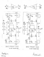
The schematic of this Amplifier was inspired by the literature of Pass Labs for its Xs amps, and the contributing literature of DIYers in this thread. Image1.jpg shows two side-by-side schematics of BA3 Front End amplifiers [cut and paste]. Their setup is meant to be balanced push-pull. Play this game with me. Partition the page into 4 quadrants care of 2 orthogonal axes smack in the middle of the page. Assume there is the highest degree of matching among/between components having the same function; e.g Q3 of both amps etc . Note the following:
Best regards
BA3 seems to be a minimalist expression of the philosophy found in the XS amps. Any thoughts?
The schematic of this Amplifier was inspired by the literature of Pass Labs for its Xs amps, and the contributing literature of DIYers in this thread. Image1.jpg shows two side-by-side schematics of BA3 Front End amplifiers [cut and paste]. Their setup is meant to be balanced push-pull. Play this game with me. Partition the page into 4 quadrants care of 2 orthogonal axes smack in the middle of the page. Assume there is the highest degree of matching among/between components having the same function; e.g Q3 of both amps etc . Note the following:
- Top right and left quadrants circuits are mirror images; identical performance.
- Ditto for bottom right and left quadrants circuits.
- The top and bottom right quadrants circuits have identical complementary symmetry performance.
- Ditto for the top and bottom left quadrants circuits
- The top right and left quadrants circuits have identical complementary symmetry to the bottom right and left quadrants circuits.
- The circuits in the top right and bottom left quadrants have identical complementary symmetry performance.
- Ditto for the circuits in the top left and bottom right quadrants.
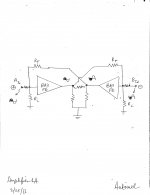
- I modeled both BA3 Front End amps with the triangles above them.
- Both amps have identical out of phase input and power output signals.
- Note the feedback loops. The power output signal of the right amp is the feedback signal to the left amp. Simultaneously, the power output signal of the left amp is the feedback signal to the right. Each amp accepts this reality because of the system's high symmetry.
Best regards
Attachments
Are you sure thats not the 8 pole Speakon?
Not very rational, it doesn't make much of a difference inside the connector.
Why put both signal and power through a single cord, just as easy to use two.
I thought earth had to be carried to every case.
For the "earth" carrying case : couple of decades ago I made a 2-case monaural class A power amp with fully regulated rails.
Based on the 50W MOSFET l'Ampli Fou (= crazy amp) design in l'Audiophile by Hephaistos. Aka Gerard Perrot of Lavardin audio in France.
(already had it in my head a couple of years before I read the article, figured it not such a bad idea after-all when I saw someone else do it
) Same principle, one case with transformer/caps and regulation stage, umbilical cord to the amp case. Second case earthed to power ground, worked fine.
(but hey, guessing is 99% of the fun, and I've been spanked by his highness before)
Not very rational, it doesn't make much of a difference inside the connector.
Why put both signal and power through a single cord, just as easy to use two.
Not talking about rationality here. Just that I don't think its a PowerCON thats on it.
To me it looks like a SpeakON 8 pole connector. Doesn't mean Papa used all the taps,
but that he can use more than just 3 wires.
Or perhaps that the SpeakON connector allows for 50A current but the PowerCON allows for only 32A
Last edited:
Oops, my bad.
You're correct, it's a Speakon, they even read Liechtenstein on the Xs pictures.
Smarter choice too, as the current rating is per contact.(30A rms x 8 beats 32A x 3)
The story was more about the 2 cases, and why.
Both amp cases are identical, the heatsinks are identical.
If all power devices were part of the output stage, 56 of them would be in either case, not 40 bottom and 72 on top.
An umbilical with 2 signal wires, one power ground and +/- power from bottom to top, plus output wires, makes no sense.
2 contacts in parallel for the positive rail, 2 for the negative one, and 4 in parallel for power ground does.


detail worth
Eeeh, no, you think it should ?
An "actively filtered PSU" can belong to the SE-part of the output stage.
Merely viewing the amp as two black boxes, with in each case a part of the output stage, the (all-in-one) umbilical makes no sense.
For a preamp it could (not there in the XP model), but for a 50A peak capable power amp ?
Violates an ampy 101 principle : high impedance and high current in parallel.
Why get into all that trouble, when a simple 2nd cable would have sufficed ?
Me simple farmer, if the tail looks & smells like rat, it's not mouse.
(and the wind direction shifted from South-East to South-Weed again)

I did find it interesting that in the Vassago page, each output board had both rails connected to it. Its a bridged bridged amp. I just love the fact that I have no idea what is happening and can just guess. Sorta like school, when the teacher would ask me if that was an answer or a question.
now XS is a Rat
Read cable code number on the posted Xs backside image : 0756 mt.
Common for cable-works is that the last digit names the number of conductors.
A 6-conductor power cord again doesn't add up (not to mention the length of that Rat fairy-tail).
- Status
- This old topic is closed. If you want to reopen this topic, contact a moderator using the "Report Post" button.
- Home
- Amplifiers
- Pass Labs
- Pass Labs Xs