Sorry about the pix, I just switched to linux on my home pc, and cannot figure out how to shrink them down to a prefered 200k....
Hi Tea-Bag,
What linux distro are you using? Most will have a program called gimp installed - if yours doesn't have it automatically it'll be easy to find and install. This is (almost) a photoshop replacement program - I love it - and it's easy to use to change file formats, alter photos et cetera. To reduce the size you open the file you want, click on "image" on the toolbar, and in the submenu that comes up you choose "scale image". This then gives you a pop-up screen
and you choose the dimensions you want.
I have used linux exclusively for all my computing needs, professional and fun, for a decade now. If you'd like help send me email so I don't pollute the thread too much....
Cheers
Nigel
I've been using xv since forever to resize images. Also the command line program "convert" which is part of ImageMagick will do a good job.
I've been using xv since forever to resize images. Also the command line program "convert" which is part of ImageMagick will do a good job.
Yes, xv will do the job too.... I didn't know about "convert", though, but for a command-line addict like me it's always good to learn new tricks
")
Cheers
Nigel
I played with the Delite again last night. It had a slight hum to it, with my ear 6 inches from the speaker, and more noticable with headphones.
I ended up curing it by adding another CRC to it.
So now its 2x 15k->1ohm->2x15k-2x5k->.5ohm->2X5k.
I seem to have lost a bit of low end when I did this. But the hum disappeared. I might reverse this configuration to see if it improves bass response. I am still skeptical if the supply resistor should be using a 1 ohm or a .1ohm, at 1 ohm, it looks like 50 watts of disappation to get the temp under control.
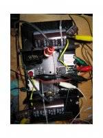
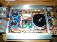
Think about the life time of the electrolytic capacitors! Mounting on the heatsink is a very bad solution. Please note:okay, maybe better picture of what is going on. Two channels working.
Takes about 20 minutes a channel to build the amp, 20 minutes for power supply. 10 minutes to clip lead.
Thanks njepitt - Got gimp downloaded. Not perfect, but can see something.
Per 10 degrees increase of temperature causes a halving of the lifetime - even by 125 degree high professional versions !!!
Think about the life time of the electrolytic capacitors! Mounting on the heatsink is a very bad solution. Please note:
Per 10 degrees increase of temperature causes a halving of the lifetime - even by 125 degree high professional versions !!!
I hear you. The output caps were put into place there because I simply was tiding up and running short on clipleads. A note, the sink doesn't heat up much in it's current implentation. This is just playing around for now.
I am thinking charging cap after or before the bulbs, with a 1-2.5k resistor to ground, from what I see in the F2 circuit. The bulbs themselves take a second or so to lightup at turn on, but its not enough to stop the thump.
Delite variation
Sorry, this will be my first time posting here. But anyways, I built this amp, but using a 20ohm resistor instead(5x100ohm/50w resistors in parallel) of a lamp. What I do not understand is that if 1.2 amp is the bias, how come I get only 2 to 3 volts across the 20 ohms load resistor? which means I only get about 150ma, and when I hooked up my scope and 1k sine wave, I get the top portion of wave cut off at about half of what is in the bottom. Distortion. Am I missing something here? Misunderstanding something? Help!
Sorry, this will be my first time posting here. But anyways, I built this amp, but using a 20ohm resistor instead(5x100ohm/50w resistors in parallel) of a lamp. What I do not understand is that if 1.2 amp is the bias, how come I get only 2 to 3 volts across the 20 ohms load resistor? which means I only get about 150ma, and when I hooked up my scope and 1k sine wave, I get the top portion of wave cut off at about half of what is in the bottom. Distortion. Am I missing something here? Misunderstanding something? Help!
I hear you. The output caps were put into place there because I simply was tiding up and running short on clipleads. A note, the sink doesn't heat up much in it's current implentation. This is just playing around for now.
I am thinking charging cap after or before the bulbs, with a 1-2.5k resistor to ground, from what I see in the F2 circuit. The bulbs themselves take a second or so to lightup at turn on, but its not enough to stop the thump.
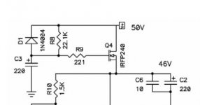
To avoid any transients after switch on (turn on, as you say) please use the electronic inductor solution as used by Andrea Ciuffoli's "Power Follower" about
the Power Folllower
Don't forget the serial diode from source to the actually +Vdd, if you choice large value of capacity from +Vdd to -V resp. GND to protect the MOSFET while switch off and while the discharging of the mentioned capacity.
And additional a suggestion of my favorite electrolytic capacitors - by the way - also for all other single ended design's best possible choice, I think:
GW2009 - FTCap Fischer & Tausche Capacitors Group
http://www.ftcap.de/downloads/elektrolyt/datenblaetter_2009/GW2009.PDF
and always the 63V versions, if the voltage supply isn't above 50 volts, but even if the max used voltage is much below 50 volts (63V versions consist still lowest values of unwanted parasitic effects).
Please call regarded your local distributor there:
Request - FTCap Fischer & Tausche Capacitors Group
If you want additional enhance of your capacitor quality, you can look my capacitor suggestions about this diyaudio thread:
http://www.diyaudio.com/forums/soli...ter-reference-amplifier-schematic-wanted.html
Last edited:
The discharge is best accomplished with a reversed diode in parallel with the cap that charges the reference capacitor.
Nelson
I think you mean the resistor that charges the reference capacitor? Just to make it clear for other members...
Erik
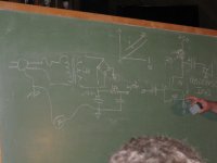
On a slightly different note looking at the blackboard photo could the
1ohm source resistor where Nelson's finger is be used as an inverting
input? It seems the perfect place to inject some of the ripple and noise
from the power supply like is done in a lot of the circuites on Tubecad.
1ohm source resistor where Nelson's finger is be used as an inverting
input? It seems the perfect place to inject some of the ripple and noise
from the power supply like is done in a lot of the circuites on Tubecad.
Attachments
Hmmm.... kind of like Ultrapathinject some of the ripple and noise from the power supply

James
It seems the perfect place to inject some of the ripple and noise from the power supply
All told I think it's a lot easier to use a slowly charging voltage
regulator / cap multiplier. It gets rid of the noise at the
source and also prevents substantial turn-on thumps.
Why not try one of Nelson's little voltage regulators for ZV3?
All told I think it's a lot easier to use a slowly charging voltage
regulator / cap multiplier. It gets rid of the noise at the
source and also prevents substantial turn-on thumps.
So, Is the ZV3 supply the best start here?, Or is there a simpler opportunity.
I am no genius with regulated supplies, and could use some help here.
I could be patient and wait for an article...
- Home
- Amplifiers
- Pass Labs
- Pass "DeLite" Amp from BAF