Thank you
")
Paradise Voltage Problem
Hai Guys,
I have a problem with my Paradise on one channel.
I installed the Calvin boards, made holes in the mainboard, and put nylon screws in.
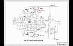
Now I have 2 Volt DC at the output. I uninstalled the Calvin Board, got rid of the old buffer (Q90,91,92,99), and now I have -13V at the RIAA output.
In the pic you can see my voltages (red ones are the ones that differ,all the other ones are perfect)
Q18 gets hot.
Can you give me a tipp what it can be? If I don't have a buffer, no original, nor Calvin, can the OPA do his job??
I don't remember if I ever measured the output dc at all. The other channel is perfect, no DC on input and output at all.
Thanx in advance!!
Hai Guys,
I have a problem with my Paradise on one channel.
I installed the Calvin boards, made holes in the mainboard, and put nylon screws in.
Now I have 2 Volt DC at the output. I uninstalled the Calvin Board, got rid of the old buffer (Q90,91,92,99), and now I have -13V at the RIAA output.
In the pic you can see my voltages (red ones are the ones that differ,all the other ones are perfect)
Q18 gets hot.
Can you give me a tipp what it can be? If I don't have a buffer, no original, nor Calvin, can the OPA do his job??
I don't remember if I ever measured the output dc at all. The other channel is perfect, no DC on input and output at all.
Thanx in advance!!
Attachments
EDIT 7 Feb:
I changed all transistors Q3/Q10/Q17/Q18/Q22, Q6,Q7,Q8,Q9,Q24
Still the same problem. Still the same voltages.
Wenn I put the Calvin Buffer in, than the Output voltage goes down to about 2V. The OPA does his work, but on the input of the Calvin there is -13V....
Audiomania
I changed all transistors Q3/Q10/Q17/Q18/Q22, Q6,Q7,Q8,Q9,Q24
Still the same problem. Still the same voltages.
Wenn I put the Calvin Buffer in, than the Output voltage goes down to about 2V. The OPA does his work, but on the input of the Calvin there is -13V....
Audiomania
Hi,
Your Method is not clear.
What have You done exactly?
I assume both channels non-modified functioned as intended?
Then You added the Buffers in both channel and one works ok, the other doesn´t?
You put a small resistor of 10R-22R into the input as dummy pickup?
You trimmed the input offset to exactly 0V with P1?
You connected the DC-Servo to the RIAA, or left it open?
You´re sure that the drilling didn´t cut any PCB trace by accident, or created a short between the layers?
Due to R9 (the DC-path from the current mirrors to ground) beeing rather high-valued and due to the current mirrors beeing very high-ohmic, every 1µA of deviation in the current mirrors idle currents (Ic of Q18 and Ic of Q7) results in 73.5mV(!) of Offset voltage across R9.
As neither matching can be perfect nor NPNs and PNPs beeing true complementaries, and resistors and other devices without perfect 0-tolerance, small deviations are unavoidable.
Your measurements show a difference between the base voltages of Q17 and Q6 of 30mV.
Hence the voltages over the emitter resistors of R4 (TP6) and R8 /TP10) will differ also by close to 30mV.
This translates to a current imbalance of 30mV*220R or 6.6mA.
My Simulations (with a 10R input dummy Pickup, Poti P1 set to 0.64 to null Input Offset) show a deviation of ~210µA between Ic(Q18) and Ic(Q7) when the DC-servo Input-resistor R48 were left open or grounded.
This results in an Offset Voltage of 210µ*73k5 [A/V] = 15.4V !!
Hence You need to activate the DC-servo, not open, not grounded.
You must connect R48 to the RIAA output to test for correct function of the Paradise wo. Buffer.
You should also test the Buffers with their inputs grounded (or connected to the RIAA output if that part works ok) and trim their Offset close to 0V at idle.
The initial Offset voltage of the Buffer should be in the low mVs range with the Offset Poti set halfways.
Larger Offsets indicate a mismatch of the Master-JFETs PF5102 or their source resistors.
If both the Paradise part and Buffer work ok, then the DC-servo maybe connected from the RIAA back to the Buffer-out again.
jauu
Calvin
Last edited:
Hello Calvin,
thanx for your reply.
Both Sides worked, I have no voltage on the Inputs, I trimmed them perfectly to 0,0mV with a 220Ohm on the input, as this is good for my cardridge.
I don't remember if or that there was an offset on the outputs before installing the Calvin Buffer. But I think, I have measured it, as my following amp is dc coupled.
I installed the Calvin Buffer and now I have -13V on the Calvin Input and Output. I can trim this Input to Output to zero.
The other channel is working perfectly. I even swapped the Calvin Boards to look if it maybe from one of those.
I did check if the drilling did something, I cleaned the drilling holes...Measured it...no problem here.
Nice greetings, Remco
EDIT:
further investigations with Calvin Buffer, 22Ohms/0,0mV on Input.
On both sides of R5, the voltages are not equal.
0,58V = 0.626V
-0,58V = -0,555V
On Pin6 of OPA: 17V
R48 connected to RIAA, gives -4V on RIAA, -17V on Pin 6 of OPA
Calvin Buffer installed, Input of Calvin connected to Ground, 0,06V on Output, 1,8V on Pin 6 of OPA
Seems like an imbalance somewhere around Q4,5, Q11-16
Hi Remco, the buffer should be inverting, means when the output is negative the voltage at pin 6 should be positive. When you write "R48 connected to RIAA, gives -4V on RIAA, -17V on Pin 6 of OPA" that would indicate the servo is broken, although from the previous comments it appeared to be working ok. Have you tried swapping the opamps?
Hi,
I simmed with the BC327-40 and BC337-40 models of Philips, OPA134 of TI, 8mA Idss for 2SK170BL and R48 connected to Riaa-out (wo. Buffer)
This resulted in +565mV and -627mV over R5, -419mV at the OPamps output and 24µV offset at the Riaa-output.
Maybe the matching between NPNs and PNPs is not tight enough, or one of the transistors is slightly off.
It may also be that the voltage generated by the JFET-current sources and the Z-Diodes differ.
The supply voltages at TP3 and TP4 may be a bit off, with the modulus of TP3s voltage beeing higher than TP4´s.
Then raising TP4´s modulus of voltage by increasing Q98s and D1s bias current may help.
You could try as a test to parallel R10 with another 1k resistor and measure if that symmetrizes the voltages over R5 and normalizes the DC-servo and the output.
In Sim it took a 410R for R10 to symmetrize over R5.
jauu
Calvin
ps. btw. a same polarity Offset at Riaa-out voltage and OPAs Pin 6 can be reproduced if the OPamp is not connected to the Riaa-out or Buffer-out.
Try (not powered circuit) measure from Riaa-out directly to OPamps Pin2 if You can measure connectivity and 1Meg resistance.
Last edited:
Hi all,
just to let you know I started a new group buy here: http://www.diyaudio.com/forums/group-buys/216891-paradise-phono-stage-116.html#post3811631
There is also the shunt regulator only, in case you need a super duper power supply for your preamp
happy hunting
alfred
just to let you know I started a new group buy here: http://www.diyaudio.com/forums/group-buys/216891-paradise-phono-stage-116.html#post3811631
There is also the shunt regulator only, in case you need a super duper power supply for your preamp
happy hunting
alfred
Check the documents accessible through my signature, its all there. BTW the output voltage of the shunt can be set through the number of LEDs you put in the string, just short-circuit a couple and you get to 15V, for example.
And this http://www.diyaudio.com/forums/group-buys/216891-paradise-phono-stage-118.html#post3812655
Output Voltage Problem
Hello Calvin and Alfred,
swapping the Opamps was the first thing I did. The -17V is a typo..-3V on Pin 2
+17V on Pin 6! (when no opamp is in than I have 0,05V on Pin 6, -15,8V at the RIAA, 14,5 at pin 2) 1Mohm perfectly there.
I got matched transistors from someone here, they were very good matched, around 1%. Maybe one got off...but which one??
I allready swapped Q6-Q10,Q17,Q18,Q24,Q22. Still the same.
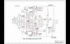
In the NEW diagram here, you can see, the Zeners are good.
I changed the voltage of +/-18,2V up and down around 0,6V. The variation of the wrong voltages is minimal. -3 going to -3,4...+17 going to +16,7...
1k over R10 did not change the voltages much.
Remco
Hello Calvin and Alfred,
swapping the Opamps was the first thing I did. The -17V is a typo..-3V on Pin 2
+17V on Pin 6! (when no opamp is in than I have 0,05V on Pin 6, -15,8V at the RIAA, 14,5 at pin 2) 1Mohm perfectly there.
I got matched transistors from someone here, they were very good matched, around 1%. Maybe one got off...but which one??
I allready swapped Q6-Q10,Q17,Q18,Q24,Q22. Still the same.
In the NEW diagram here, you can see, the Zeners are good.
I changed the voltage of +/-18,2V up and down around 0,6V. The variation of the wrong voltages is minimal. -3 going to -3,4...+17 going to +16,7...
1k over R10 did not change the voltages much.
Remco
Attachments
Remco, please try and put 50kOhm resistors in parallel to R43a and R43b - this will increase the servo's "authority". If the output voltage then goes to zero, the circuit is basically working fine, and you have a rather large source of offset somewhere in the circuit. But at least we would know that it is working.
The servo is made very "weak" on purpose.....
The servo is made very "weak" on purpose.....
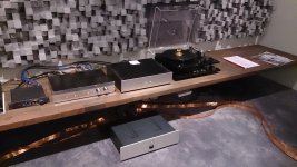
Here is a picture from a hearing session I had last week. The system was a Goldmund TT with DL103R, the Paradise, preamp from Orange Audio, power amp from Counterpoint, loudspeakers Roksan Darius.
We swapped a few records, and settled on "coal train" from Hugh Masekela, and compared the Paradise with a (older) Goldmund phono stage, the built-in phono stage from the preamp, and (yes!) the MP3 version.
Needless to say Paradise won hands-down. It was as if the lights are turned on in the room, and you could almost "see" the instruments, with a totally "right" and "clear" and "true" feeling to every acoustic event. Deep soundstage and perfect tonality.
Had to leave the Paradise with my friend, and I wonder if I will ever get it back
Attachments
- Home
- Source & Line
- Analogue Source
- Paradise Builders