Right - so where is there anything there 'dissing' Bill Whitlock or THAT?The quote made. You are complaining that the internal circuitry is class B and therefore will sound awful without your preferred PSU mods.
How do you know its under 120dB down when music's a stimulus? All you have are THD+N figures, with sinewave stimulus. Oh and IMD, twin tone.
You stick to glomming regulators on £5 boards on the internet and blogging about SQ. I'll continue to believe that anything more that 120dB down is really not my problem.
You are complaining that the internal circuitry is class B and therefore will sound awful without your preferred PSU mods.
You're more than welcome to swallow your own rhetoric
")
"I've had circuits that worked flawlessly as long as the incoming slew rate was limited and the output voltage stayed away from the supply rails. Drive the input too hard or drive the output too close to the rail and all hell would break loose. For me, that's a "back to the drawing board" experience.
That the circuit can produce a sine wave with low THD is in itself rather meaningless if it can't handle being overdriven momentarily."
It is nice that Tom had brought up these points, in all his pure goodwill to help.
So as we can have a look of the shots below here and in the original thread where it is published since quite a while..
http://www.diyaudio.com/forums/chip-amps/234032-my_ref-fremen-edition-build-thread-tutorial-231.html
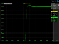
In the first the amp is hit with a signal with 5nsec rise time, and is driven 2V below the clipping limit, it is slewing with it's max slew rate 11.6V/usec, gets out of the nonlinear phase without a hitch, totally smooth and settles in ~13usec total. Hell did not break lose. Checkmark OK!
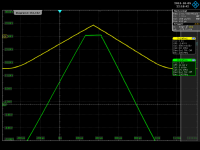
In the second it is driven in deep overload, clipping, hell did not break out, checkmark OK.
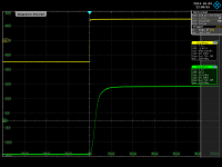
In the third it gets out of clipping with real minimum sticking. Checkmark?
Can we call back Mr. Penasa from the drawing board and place him at the right spot, on the kathédra of the teacher?
Can we forget for Ever, about these nonsense accusations?
Sincerely, George
That the circuit can produce a sine wave with low THD is in itself rather meaningless if it can't handle being overdriven momentarily."
It is nice that Tom had brought up these points, in all his pure goodwill to help.
So as we can have a look of the shots below here and in the original thread where it is published since quite a while..
http://www.diyaudio.com/forums/chip-amps/234032-my_ref-fremen-edition-build-thread-tutorial-231.html
In the first the amp is hit with a signal with 5nsec rise time, and is driven 2V below the clipping limit, it is slewing with it's max slew rate 11.6V/usec, gets out of the nonlinear phase without a hitch, totally smooth and settles in ~13usec total. Hell did not break lose. Checkmark OK!
In the second it is driven in deep overload, clipping, hell did not break out, checkmark OK.
In the third it gets out of clipping with real minimum sticking. Checkmark?
Can we call back Mr. Penasa from the drawing board and place him at the right spot, on the kathédra of the teacher?
Can we forget for Ever, about these nonsense accusations?
Sincerely, George
Attachments

Last edited:
Can we forget for Ever, about these nonsense accusations?
Sincerely, George
Tom was asked to comment on the original Pensa document, which he did. Bringing new evidence to bear without asking him to comment as well seems odd.
Just let me repeat. I don't think I could tell the difference between them in a blind test.
I will have to start calling you 'Mr Pot' again.
Please do go ahead and do so, you have my full permission (not that you need it, of course).
Bringing new evidence to bear without asking him to comment as well seems odd.
An invitation to comment isn't required, nor does it seem at all odd one hasn't been given - if he wants to rebut he's free to do so.
Tom was asked to comment on the original Pensa document, which he did. Bringing new evidence to bear without asking him to comment as well seems odd.
Just let me repeat. I don't think I could tell the difference between them in a blind test.
Bones to pick A?!
I think it might be better for TOM to defend himself and eat crow if need be..
as they say your showing your ***
have a nice day
I did not bring up anything new. In fact, all this mantra about supposed instability of the amp is something which is going on since ever, from Tom's part. He could have seen the results posted months ago.
The fact that he continues with it just renders the situation funny, because other people, maybe really interested, can just deduct their own conclusion...
Sincerely, George
The fact that he continues with it just renders the situation funny, because other people, maybe really interested, can just deduct their own conclusion...
Sincerely, George
Member
Joined 2009
Paid Member
+1
Having built a My_ref Rev C, I realize that I'm biased, but I don't understand why the My_ref family gets largely forgotten in discussions like this. It is one of the best designs available and was developed in this forum.
I haven't got around to building anything like this (yet...) but I must say I was very impressed with the work of Penasa. In my view, based on 5 years of 'work' in this hobby, this My-ref approach is very innovative and worthy of very high praise. It is one of the few truly great circuits that I've seen around here.

I had thoughts about a hybrid, with the outside loop/front opamp being replaced with hollow-state but using the current pump output - just for fun of course
And the SNR of this thread dropped off precipitously. :/
Clearly everyone has their pet favorite projects and takes exception to everyone else's favorite project. There's enough room for all types without Calvin ******* on respective hood ornaments, K?
Not that the OP is interacting with the thread much anymore, but if he needs a parallel chip design (since 4780 is no more), then his options are much more limited. And he should pay attention to his gain structure, as there's a pretty wide range, and whatever matches the rest of his system best will *probably* give the best option. They're all competent enough that plenty of folks have had success building them.
Bones to pick A?!
I think it might be better for TOM to defend himself and eat crow if need be..
as they say your showing your ***
have a nice day
No bones to pick. I have said I don't think I could tell the difference and stated what I have built and why. But Tom was asked to comment on a link and he did. As an engineer he took the request literally and commented on that orignal paper. all the myref defenders (bar Cave ) are leaping up to claim 'ah but he should have commented on something that he should have known existed'. I, using my free speech pointed out that Tom wasn't asked to comment on those.
Clearly this puts me down as picking sides and some sort of mod86 fanboi. Not sure why. I have never said the Myref was bad. Never said a mod86 sounded better. Just pointing out SIMPLE LOGIC.
But on the internet many only see black and white. No grey, no being reasonable.
You certainly write well in a non-native language, better than most natives!
Thank you. I started learning English when I was in fifth grade (1985). I've worked hard at it and have been living in an English-speaking society for nearly two decades. That does help...
I'm sorry that I ended my post with a negative personal comment, especially because that's what seems to have made the most impact.
No worries. Let's move forward.
Because you're a professional designer, I understand why you must be more concerned with measurements and specifications than with people's impressions. Your design focus certainly reflects that, as well as other valid engineering principles, and I admire that. However, if a hundred people tell you that something sounds not just good but extraordinary, people who have experience with the subject and at least some degree of self-criticism, wouldn't you be a little curious about the validity of their statement?
Now, I am aware that I'm opening op a Costco sized can of worms here. There is a lounge thread of measurements vs perceived sound quality that we could direct this aspect of the conversation if that's more in line with everyone's desires here.
The reason I rely on measurements is that they're repeatable and have high validity. I.e. you get the same result if you measure the amplifier today as you did last night. You get the same results whether the amplifier is painted blue or red. Validity deals with whether the measurements measure what they claim to measure. I am confident that when AP says the software measures IMD, then it does that. So I have confidence is my measurements.
There is a large body of research which points to a strong correlation between measurements and perceived sound quality. Belcher (1978) is an example of such research. He lists THD as one indicator of perceived sound quality, albeit, not a very reliable one. He suggests using a multi-tone test as that gives better correlation between the perceived sound quality and the measured parameter. That's one example I'm aware of that's accessible to anyone. Sean Olive has written about this in great length as well. Harman Kardon used to have his papers on their website, but last I checked, they'd been removed. Sadly, this means this kind of information is either behind a paywall or corporate confidential. Still, a good amount of information in Olive's blog is still available (or was last I checked, I should say).
I have a fundamental problem with basing design decisions on perceived sound quality. One of these problems is the vocabulary. Two people will hear the same sound but perceive two different things. For example, one person may hear the high-Q resonance of a metallic speaker cone's break-up and say, "wow! This is really precise" (positive experience). Another listener may say, "dang! That's really harsh" (negative experience). They're hearing the same thing. Who's right?
Then you have reviewers who add a solid dose of ambiguity by using words like soft, fast/slow, melodic, tempo, veils lifted, etc. without quantifying what those terms mean.
Then think a little about groupthink and how that plays out in a sighted test between friends. A: "Wow! That's really obvious! Can you really not hear that?!" B: "Well, I guess I do hear something". It's the famous "wife came running from the kitchen asking if I'd changed something" testimony. I forget if it's SY or Wavebourn who has a brilliant write-up on how he, unintentionally, ended up classically conditioning his wife to provide that response because he always used one particular track as a test track but wouldn't normally listen to it.
In summary: Conflicting experiences, too much ambiguity -> no reliability and questionable, if any, validity.
Now, the perceived experience is important. But the perceived experience is subject to all sorts of interesting cognitive biases. If you're interested in that sort of stuff, I recommend Dan Ariely, "Predictably Irrational". Ariely deals with the cognitive biases from a business perspective. Olive & Co. did some work on how the perception by other senses (sight) as well as other parameters (such as price or brand) impact the perceived sound quality. In a sighted test, pretty or "high end looking" equipment sounds better on average. Similarly, in a sighted test, equipment with a high price tag sounds better on average.
Anyway. I can go on about this but I think I've made my point. With the ambiguity and conflicting nature of the language used to describe the perceived sound experience, I don't have reliable data to make a design decision.
With objective measurements, I do have reliable data to make design decisions, hence, I rely on measurements for my design decisions. Given the correlation between good measurements (plural!) and a positive perceived sound experience, I am confident that when I'm done building I will have an amplifier that sounds good. This scientific process allows me to be more efficient in my workflow, which means better products in the customers hands faster.
With so much disagreement about what measurable parameters constitute an amplifier that actually sounds good as well as accurate ("we" can't even agree if that's exactly the same thing), shouldn't there be room for doubt that an amplifier (or any piece of audio equipment) that measures better always SOUNDS better or even as good?
Among audio scientists, I doubt there's much disagreement, actually. It's in the DIY and enthusiast communities you find the disagreement. Some of the disagreement is fuelled by scrupulous marketeers who dazzle you with superlatives to sell their speaker cable stands or whatever. For more examples, see the Snake Oil thread in the lounge.
It's asking a lot of a dedicated professional, but I hope you can admit that at least the possibility exists.
Sure. I'll even give you an example. My DG300B has a THD of about 0.2 % at 1 W, 1 kHz, 8 Ω. That's pretty good for an SET amp with no global negative feedback, but it would be a do-over for a solid state amp. I think the DG300B sounds good and my customers back me up on this in their testimonials. It's a pleasing and laid back presentation but it doesn't sound precise - and it shouldn't. After all, the customers are after that "sweet 300B sound". My design philosophy was the same, though: Design an SET amp that uses the 300B tube and provides the best measured performance possible under those constraints. The end result is an amp that sounds like it has high THD at the lower frequencies (harmonic extension -> bass emphasis) and is a little slew-rate limited. That's what a good 300B tube amp sounds like and measurements back up this claim.
I hope you're willing to accept that your senses can fool you, including your hearing. The ways they fool you are plentiful and have been well characterized.
If you need of an example of an auditory illusion, just think of the stereo image. You can hear different instruments placed at different spots in the room between the speakers, but there is no sound source at that location. Your senses are fooling you into believing that you're hearing something from that location. I'm not saying that's a bad thing. I'm just saying that your senses aren't as reliable as you think they are.
People are humans, hence, are subject to various biases. In part, that's what makes psychology fun.
Tom
Absolutely, I like and support your approach, nevertheless clipping counter-measures have been taken in the original design (limiting LM318 rails) and refined in the My_Evo (zener limiter, see figure 5b from this link).
Awesome. Thanks for providing the link.
Nevertheless the 0.00011% THD measured by JosephK say it's not that much detrimental, after all
I'm assuming this measurement is the FFTs you provided. Thanks for those, by the way. The measurements were taken at about -12 to -15 dBFS. There's no mention of what the full scale (FS) voltage was, but I'm guessing you're using a computer sound card (hopefully an external one!), so the full-scale voltage is either 0.9 V RMS or 2 V RMS. I'll assume an external sound card and go with 2 V RMS = 0 dBFS.
-12 dBFS would then be 0.5 V RMS. -15 dBFS would be 0.356 V RMS. Assuming an 8 Ω load, this means you're measuring at an output power in the range of 16 mW to 31 mW. You won't see the effects of the zener limiter or many other non-linearities under those conditions.
It could also be that a voltage divider was used and the vertical scale wasn't changed to reflect this. It's unknown at this point.
I would appreciate it if you'd ask the guy who took the measurements to provide the reference for 0 dBFS.
I'd like to see the THD measured at 1 W and at the full rated output power. THD vs frequency and THD vs output power would be a nice touch as well.
Penasa always stated that it was a DIY release, not ready for commercial level.
Totally fair.
That doesn't mean that it's not stable or suitable for an high quality DIY amp.
Absence of evidence is not evidence of absence. I think the circuit has potential and provides a good starting point for a DIY experiment. I would look at some things, including stability, either with a circuit simulator or with a network analyzer before I made any blanket statements about stability. All I have done - or at least all I intended to do - is to raise my hand and say, "um, you might want to take a look at stability". That's all.
It should be the power wasted by the output resistor (remember the 'improved' HCP?).
You burn 20 W in the output resistor? That sounds high. I suggest doing the math. I bet something else is going on. Not sure what, but it's something I'd look at either in the circuit simulator or on the bench.
Really interesting, I appreciate it
Cool! Well, I'm glad the two of us at least are getting along.
Tom
I think it might be better for TOM to defend himself and eat crow if need be..
Or pick my battles and go engage in more productive and rewarding activities than an Internet peeing contest.
I did not bring up anything new. In fact, all this mantra about supposed instability of the amp is something which is going on since ever, from Tom's part.
From my part? Bob Pease wrote about instability in Howland Current pumps way before I was even aware of the existence of the circuit, never mind the MyRef. I've provided the link to his app note earlier in this thread. All I'm saying is, "uh, guys. You may want to take a look here".
Thanks for posting the slew plots. That relieves that concern.
Fremen asked me for my opinion on a document. He asked twice (because I put it off the first time). I provided my opinion. He seems OK with it, so I'm not sure why the rest of you are so spun up about it.
Tom
Awesome. Thanks for providing the link.
You're welcome.
I'm assuming this measurement is the FFTs you provided. Thanks for those, by the way.
Yes, it is.
My pleasure.
The measurements were taken at about -12 to -15 dBFS. There's no mention of what the full scale (FS) voltage was, but I'm guessing you're using a computer sound card (hopefully an external one!)
(...)
You won't see the effects of the zener limiter or many other non-linearities under those conditions.
It could also be that a voltage divider was used and the vertical scale wasn't changed to reflect this. It's unknown at this point.
(...)
I'd like to see the THD measured at 1 W and at the full rated output power. THD vs frequency and THD vs output power would be a nice touch as well.
JosephK measured distortion at various power levels, maybe you missed the links I've provided (again...
):You can find complete My_Evo JosephK measurements here and Fremen Edition here.
You will find all the graphs of the measurements (THD, THD+N, IMD and so on)
I would appreciate it if you'd ask the guy who took the measurements to provide the reference for 0 dBFS.
For you convenience this is the link to the complete set in PDF posted by JosephK for the Fremen Edition.
BTW you can ask him directly, he's a nice guy.
Absence of evidence is not evidence of absence. I think the circuit has potential and provides a good starting point for a DIY experiment. I would look at some things, including stability, either with a circuit simulator or with a network analyzer before I made any blanket statements about stability. All I have done - or at least all I intended to do - is to raise my hand and say, "um, you might want to take a look at stability". That's all.
Raising hands is fine, simply it will be easily accepted if you document yourself a bit before and give at least the benefit of doubt to the (competent) designer.
This has been the main reason for asking you to read Penasa's document.
Your thorough scrutiny has been an appreciated plus.
Mauro Penasa already did years ago all that homework of design, testing and measurements.
I've attached another example (sorry Italian only...) maybe you can read it using some translation tool.
You burn 20 W in the output resistor? That sounds high. I suggest doing the math. I bet something else is going on. Not sure what, but it's something I'd look at either in the circuit simulator or on the bench.
You're right, the output resistor (specced at 5W) is only part of it, probably a big part of the power waste is due to the use of the LM3886 as a current pump.
For sure it's not the most efficient design but the end result is somewhat stunning.
If you're curious about it I would happily send you for free a couple of boards from the current GB, but:
- you'll build them according the published BOM and following mount instructions (which includes mounting resistors and capacitors according a direction)
- take some measures on them.
Cool! Well, I'm glad the two of us at least are getting along.
Collaboration and mutal respect makes the golden path to learn from each other.
Attachments
Some Mauro's measurements from the first prototype posted on the original thread:
http://www.diyaudio.com/forums/atta...diophile-lm3886-approach-my-ampli-perform.zip
http://www.diyaudio.com/forums/atta...hile-lm3886-approach-my-ampli-anoder-perf.zip
Read the four post starting from this one:
http://www.diyaudio.com/forums/chip-amps/54571-my-audiophile-lm3886-approach-2.html#post683346
JosephK measured distortion at various power levels, maybe you missed the links I've provided (again...
I did notice the links, but did not follow them. I have about seven different projects going right now, so I chose to look at the information you provided directly. I just looked at your .pdf with measurements. Pretty decent amp. Congratulations.
I would be interested in your interpretation of the multi-tone measurements.
The only outstanding issue for me at this point is stability. It seems the only way I will get an answer there is by playing with the circuit in the simulator. I can do that, but it is not a priority right now.
Raising hands is fine, simply it will be easily accepted if you document yourself a bit before and give at least the benefit of doubt to the (competent) designer.
My resume is available for anyone to see on my website. It's a bit outdated, but it does sum up my background pretty nicely. For those, like me, who don't follow links, here's a summary:
Bachelor of Arts in Psychology (exp. 2018), University of Calgary.
2012-Present: Neurochrome: Precision Analog Circuit Design.
2005-2015: National Semiconductor, Texas instruments: Precision Analog Circuit Design Engineer.
Master of Science in Electrical Engineering (2002), University of Washington
Bachelor of Science in Electrical Engineering (honours, 1999), Engineering College of Copenhagen.
During the time 2002-2005, I was working on my PhD in electrical engineering at University of Washington. I wasn't really getting anywhere with it and when offered an internship with National Semiconductor, I jumped ship.
In various threads I've tried various things. I've been accused of using the appeal to authority fallacy when I've mentioned my credentials. In this thread, it seems to be the opposite. We'll see where it goes from here...
You're right, the output resistor (specced at 5W) is only part of it, probably a big part of the power waste is due to the use of the LM3886 as a current pump.
That sounds more plausible.
If you're curious about it I would happily send you for free a couple of boards from the current GB, but:
- you'll build them according the published BOM and following mount instructions (which includes mounting resistors and capacitors according a direction)
- take some measures on them.
Deal! I'll sort the details out with you via PM. Thank you for the offer.
Collaboration and mutal respect makes the golden path to learn from each other.
Agreed.
Tom
Dear Tom,
I have enjoyed the above analysis. Your's logic is crystal clear, but your memory.. hmm.. may I permit a bit of, and almost friendly, irony here..?
your memory is not that strong.. The above 'analyzed' FFT graph was already shown to You, personally adressed to You, with all the necessary annotations about applied power etc..
http://www.diyaudio.com/forums/chip-amps/279458-modulus-86-fremen-edition-8.html#post4451246
) )
Also myself like to read 'into' displayed graphs..
like, for example, the graph of mine about the slew rate. What else can be understood from that? The yellow trace shows the generator signal, green is the output. The green trace reads +-23V, 46Vpp; the generator trace reads a dot below 1.5V, ~1.45V input level. The amplification factor results to be A=31.72, ~30.03dB.
Now from the BOM of Myref we know that Rf=12kohm; Rg=390ohm.
A=1+Rf/Rg, 1+30.76, 30.037dB...
Ciao, George
The measurements were taken at about -12 to -15 dBFS. There's no mention of what the full scale (FS) voltage was, but I'm guessing you're using a computer sound card (hopefully an external one!), so the full-scale voltage is either 0.9 V RMS or 2 V RMS. I'll assume an external sound card and go with 2 V RMS = 0 dBFS.
-12 dBFS would then be 0.5 V RMS. -15 dBFS would be 0.356 V RMS. Assuming an 8 Ω load, this means you're measuring at an output power in the range of 16 mW to 31 mW. You won't see the effects of the zener limiter or many other non-linearities under those conditions.
It could also be that a voltage divider was used and the vertical scale wasn't changed to reflect this. It's unknown at this point.
I have enjoyed the above analysis. Your's logic is crystal clear, but your memory.. hmm.. may I permit a bit of, and almost friendly, irony here..?
your memory is not that strong.. The above 'analyzed' FFT graph was already shown to You, personally adressed to You, with all the necessary annotations about applied power etc..
http://www.diyaudio.com/forums/chip-amps/279458-modulus-86-fremen-edition-8.html#post4451246
) )Also myself like to read 'into' displayed graphs..
like, for example, the graph of mine about the slew rate. What else can be understood from that? The yellow trace shows the generator signal, green is the output. The green trace reads +-23V, 46Vpp; the generator trace reads a dot below 1.5V, ~1.45V input level. The amplification factor results to be A=31.72, ~30.03dB.
Now from the BOM of Myref we know that Rf=12kohm; Rg=390ohm.
A=1+Rf/Rg, 1+30.76, 30.037dB...
Ciao, George
Attachments
Last edited:
I just looked at your .pdf with measurements. Pretty decent amp. Congratulations.
Thanks
I would be interested in your interpretation of the multi-tone measurements.
Sadly my competence is limited so I'm not able to give you one...
The only outstanding issue for me at this point is stability. It seems the only way I will get an answer there is by playing with the circuit in the simulator. I can do that, but it is not a priority right now.
The LM3886 spice model is incomplete and doesn't work with the My_Ref topology, sadly.
LinuxGuru had some success simulating it using the LM1875 model.
My resume is available for anyone to see on my website. It's a bit outdated, but it does sum up my background pretty nicely.
(...)
We'll see where it goes from here...
Tom, I already know, admire and respect your credentials, as most of us... You missed the point...
I was referring to documenting yourself about the project you're scrutining and his designer... not about the theory or practice that you already know better than most of us.
Deal! I'll sort the details out with you via PM. Thank you for the offer.
Perfect! You're welcome.
I'll wait your PM.
- Status
- This old topic is closed. If you want to reopen this topic, contact a moderator using the "Report Post" button.
- Home
- Amplifiers
- Chip Amps
- PA03 vs Parallel 86 vs Sympatico vs ??