BTW the Howland current pump used is the 'improved' version and the project specify 0.1% resistors for the pump so those 'problems' are mostly 'fixed'.
Key term: "mostly". All I'm saying is that the Howland current pump is notorious for having stability issues. If you do decide to build such a circuit, be careful. Then again, I'm used to a production environment where I need to make a million copies of a circuit work flawlessly and bad things will happen if the customer ever finds a circuit that doesn't meet the specs. That's a rather different philosophy from a typical DIY perspective where building one circuit that works most of the time is often good enough. I tend to apply a "production" mindset to the products I offer for sale to the DIY crowd.
In both the My_Evo and my variation the My_Ref circuit achieve distortion level around 0.00011% (THD), not so bad for a flawed circuit...
I've had circuits that worked flawlessly as long as the incoming slew rate was limited and the output voltage stayed away from the supply rails. Drive the input too hard or drive the output too close to the rail and all hell would break loose. For me, that's a "back to the drawing board" experience.
That the circuit can produce a sine wave with low THD is in itself rather meaningless if it can't handle being overdriven momentarily.
Not an universal truth but usually most opamps have less distortion when used as inverting amps.
Tom, who is also an opamp designer, could confirm, I guess.
Yeah, I designed precision op-amps and other precision analog circuits for a living for a bit over a decade.
I've seen examples of op-amps that would actually have better THD if used non-inverting, so there's no universal rule.
The LM3886 does provide lower THD in inverting configuration (see data here). In a composite amp, I would argue that the difference isn't meaningful as the overall THD will be suppressed by the loop gain of the error correction amp.
Tom
Last edited:
Key term: "mostly". All I'm saying is that the Howland current pump is notorious for having stability issues. If you do decide to build such a circuit, be careful.
Tom, don't take so seriously my 'mostly'... I was referring to the general topology.
Using the improved topology with precision resistors the HCP is easier to deal with and the various compensation networks used by Penasa make stable the circuit.
You didn't ask my question, though... did you read Penasa's circuit description I've attached earlier?
I've had circuits that worked flawlessly as long as the incoming slew rate was limited and the output voltage stayed away from the supply rails. Drive the input too hard or drive the output too close to the rail and all hell would break loose. For me, that's a "back to the drawing board" experience.
Absolutely but it's not the My_Ref case... compensation networks are there to insure stability (limiting bandwidht and/or slewrate, eventually) and LM318 rails are kept to 12V to avoid output voltages near the LM3386 rails (original version).
In the My_Evo and Fremen edition LM318 rails are 14V but a 28Vpp output voltage limiter is present.
That the circuit can produce a sine wave with low THD is in itself rather meaningless if it can't handle being overdriven momentarily.
Again, absolutely, but it's not the My_Ref case...
Mauro Penasa is a competent Electronic Engineer who works in the electro-medical field, not an hobbyst, do you really think that he would have released to the community a circuit marginally stable or stable only 'most of the times'?
I've seen examples of op-amps that would actually have better THD if used non-inverting, so there's no universal rule.
The LM3886 does provide lower THD in inverting configuration (see data here). In a composite amp, I would argue that the difference isn't meaningful as the overall THD will be suppressed by the loop gain of the error correction amp.
Thanks for sharing
")
You didn't ask my question, though... did you read Penasa's circuit description I've attached earlier?
Just did. On the last page he says directly that he is aware that the circuit will be unstable near clipping. He goes on to say that he knows how to fix it, but didn't "feel like it" as he doesn't consider stable recovery from clipping to be a design priority. Basically, he says that you shouldn't drive the amp to clipping anyway, so why are you concerned about recovery from clipping?!
That's a flawed argument. I have seen several examples of circuits where they'd break into oscillation because they reached clipping and remain oscillating even after the input voltage was lowered. In some cases, the amp would run just fine at low volume, but you hit clipping once and you'd have to turn the amp off to make the oscillation stop. By my standards, that's not a reliable design.
In the My_Evo and Fremen edition LM318 rails are 14V but a 28Vpp output voltage limiter is present.
.... or you could just design the circuit right to start with. Just saying.
I've looked at limiters to prevent clipping. It is possible to get a limiter to prevent the amp from reaching clipping, but all limiters I've looked at have caused a significant degradation in THD well before they reached the desired limit. That's not desirable to me as I'm aiming for low THD up to clipping.
Mauro Penasa is a competent Electronic Engineer who works in the electro-medical field, not an hobbyst, do you really think that he would have released to the community a circuit marginally stable or stable only 'most of the times'?
I certainly hope not, but I can't speak for him or account for his thought process.
His statement in the design doc that he knows the topology has stability issues near clipping, knows how to solve the issues, but chooses not to solve the issues because it isn't "convenient" and would "compromise the final quality" says to me that he's either tired of the project and wants to move on, or he hasn't found a solution that works reliably without degrading the overall performance of the circuit. To me, that's "work in progress" rather than a release worthy circuit.
In my engineering education and career, I have seen many examples where designers became attached to a sub-optimal design. They invest so much time perfecting the design that they become emotionally attached to it. In those cases, it can be very hard for the designer to let go and perform a full redesign even when it turns out that a redesign is needed to move from a local optimum to a global optimum. As a circuit designer, I've had that experience. It can be very painful to realize that even though you thought you were done, you now have to go back to the drawing board and beat your head against the wall some more. In my case, the end product has always been better than the intermediate result, so in that sense the redesign has been warranted and worth the extra effort. That doesn't make it a fun process, though.
The specs at the end of the document do not make sense.
40 W @ 8 Ω, ±37 V is way low. You should get over 50 W.
56 W @ 4 Ω, ±37 V. Why? At ±28 V, you should get over 65 W, so why are you only getting 56 W at ±37 V?. What's going on there?
Damping factor, 8 Ω = >200 (frequency and compensation dependent)??! Okay... So under which conditions were the >200 DF measured? Last I checked, DF = RL/Zout and Zout for a current source should be very high. Is the circuit even a current source then? It's marketed as one...
S/N (600 Ω): >90 dB (compensation dependent). Again. Under which conditions? The SNR of the MOD86 is 112 dB. That's right at the hairy edge of detection for the APx525.
THD, IMD < 0.05 %. Yeah. Not impressed. I'm getting 0.000067 % THD (1 kHz, 38 W, 8 Ω, ±28 V) and 0.00069 % IMD (SMPTE, 60 Hz + 7 kHz, 38 W, 8 Ω, ±28 V) on the MOD86.
I'd be interested in seeing the THD+N vs frequency and THD+N vs output power for the circuit as well. The THD+N vs frequency will tell you a lot about the layout, as well as the circuit. I'm curious for the THD+N vs power to see the effects of the clipping circuit you mention.
I hope my review of your document was as thorough as you expected.
Tom
Tom,
Can you graciously accept that there is another amplifier design using the LM3886 that sounds good and is stable in hundreds of builds? No one has EVER reported a MyRef locked in oscillation or any other type of distortion or noise, and they are eminently stable into some difficult loads. Must you trash anything that sits beside your creation? We accept that your design is good, but it is not the only good design. This is not a contest that you need to win. Until you build one yourself and listen to it, there is no way to declare one is audibly superior to the other. You are very close to commercial promotion here, which is frowned upon.
Regards,
Tom E
+1
Tom,
Can you graciously accept that there is another amplifier design using the LM3886 that sounds good and is stable in hundreds of builds? No one has EVER reported a MyRef locked in oscillation or any other type of distortion or noise, and they are eminently stable into some difficult loads. Must you trash anything that sits beside your creation? We accept that your design is good, but it is not the only good design. This is not a contest that you need to win. Until you build one yourself and listen to it, there is no way to declare one is audibly superior to the other. You are very close to commercial promotion here, which is frowned upon.
Regards,
Tom E
Can you graciously accept that there is another amplifier design using the LM3886 that sounds good and is stable in hundreds of builds? No one has EVER reported a MyRef locked in oscillation or any other type of distortion or noise, and they are eminently stable into some difficult loads. Must you trash anything that sits beside your creation?
I'm perfectly willing to accept that there are other amplifier designs in the world. Some of them are good. Some of them are not. Some fall in between. I believe mine is good and have the data to back up my claims. I base my claims on facts rather than beliefs. I'm sorry if that ruffles the feathers for some.
I was asked to provide feedback on the document that Fremen attached, so I did. Should I have lied and said I thought the design was wonderful when I do in fact see several potential issues that I would like to see addressed? That would be irresponsible and bad engineering practice. Not my style.
Fremen asked for my feedback .... twice. I thought he deserved a response.
Until you build one yourself and listen to it, there is no way to declare one is audibly superior to the other.
I disagree with you there. To determine whether the perceived sound quality of one amplifier is superior to that of another, you need to set up a controlled experiment. This means a significant number of participants, controlled conditions, random assignment, etc. Folks like Sean Olive and Floyd E. Toole make a living doing this sort of stuff and the number of participants are in the hundreds in most of their work. I don't have those resources available, so I rely on measurements. There are volumes written about the correlations between good measurements and good perceived sound quality.
Rather than taking offence, you could choose to see my comments as an opportunity to improve the circuit. Include those improvements in MyRef Rev. H.
Tom
Last edited:
To determine whether the perceived sound quality of one amplifier is superior to that of another, you need to set up a controlled experiment. This means a significant number of participants, controlled conditions, random assignment, etc. Folks like Sean Olive and Floyd E. Toole make a living doing this sort of stuff and the number of participants are in the hundreds in most of their work.
I'm aware of the Harman guys doing this with speakers. Do you have any references for them using blind listening on amps?
Also in my understanding blind listening tests are used to determine audible differences. But you mentioned 'superiority' above- do you have any references to how to determine superiority in blind tests?
I'm aware of the Harman guys doing this with speakers. Do you have any references for them using blind listening on amps?
Why would they use a scientific method to determine the sound quality of speakers and a different method (non-scientific?) to determine the sound quality of an amplifier? That argument makes no sense.
Also in my understanding blind listening tests are used to determine audible differences. But you mentioned 'superiority' above- do you have any references to how to determine superiority in blind tests?
Sounds like you're looking for a nit to pick. I'm not surprised. Have fun with that.
Tom
That argument makes no sense.
Sure. Its not the argument I'm making - its entirely of your own creation.
Your later comment - ditto.
You're the one here whose feathers are ruffled and taking offense. No one is criticizing your design work, so stop cutting on other's. You already stated the case for your design. You already have one entire thread dedicated to your amp. This one need not be. You apologized a few pages back for taking over. Did you mean it?
Your passion for this pastime is admirable. Your thin skin is not.
Regards,
Tom E
Your passion for this pastime is admirable. Your thin skin is not.
Regards,
Tom E
No one is criticizing your design work, so stop cutting on other's.
Actually I did, way back when Tom first announced his design. If you want the link, I'll post it on here. The funny thing is - he took offense, rather than follow his own advice just given to you
I tried to edit the previous post, but the 30 minute window closed so I pasted the edit here instead. Please forgive the repetitions.
I will defend Mauro because he is not here to defend himself. With that in mind, you should respect his capabilities whether you agree with him or not. He does not speak or write English very well, so I am sure his documentation is not suitable for peer review, especially as it was not formally submitted. It is suitable as a guideline, probably not as a specification. You boast regularly about your professional career and your education and experience, and we all respect that. I suggest you exhibit a little professionalism and maturity. Your squabbling with and parsing of an old, imprecise document is tiresome, as is your self-promotion for profit.
Mauro did a great service to the members of this community by contributing his design free of charge for anyone interested in it, and many people were and still are interested. There is a reason for that, and it has little to do with measurements other than those made by the human ear. We're not all fools, and most of us don't need a bunch of guys in lab coats telling us what sounds like the accurate reproduction of music. I've heard plenty of good and not so good amplifiers, as have my friends. We all agree that the MyRef is something special, and so does almost every one of the hundreds of others who has ever built one. That is more convincing than reading about any number of someone else's blind tests. Can it be improved? Perhaps, but at what cost and level of complexity? Though many others have tried, Dario has gone further toward improving it than anyone else, and his efforts should not be dismissed, especially since he has provided all his service and knowledge free of charge.
No one is criticizing your design work or its implementation. You already stated the case for your design, and you already have one entire thread dedicated to selling and building your amp. This one need not be. You apologized a few pages back for taking over. Did you mean it?
Your knowledge of and passion for this pastime is admirable. Your thin skin and sense of superiority is not. Now I am getting a bit defensive, so I'll quit.
Regards,
Tom E
Your thin skin and sense of superiority is not.
Please spare me your psychoanalysis and personal attacks. I don't believe that I'm superior to anybody. I do believe that I possess some core competencies resulting from a 35+ year long interest in electronics, formal education on the topic, and industry experience in precision analog circuit design for a major semiconductor manufacturer. That does not make me a better human than any other human on the planet, but it does make me a good circuit designer.
As I said earlier: I base my claims about the performance of my circuits on measured data rather than personal beliefs.
My first language isn't English either. I had no issues with the language in the design document. I had issues with the incomplete information provided. That has nothing to do with any language barrier.
I was asked twice to provide my opinion on the design document. The second time I was asked, I did provide my opinion. Could I have been more diplomatic in my use of language? Sure! Sorry. I'm a human too. My life contains stressors just as anybody else's.
Tom
Last edited:
You certainly write well in a non-native language, better than most natives!
I'm sorry that I ended my post with a negative personal comment, especially because that's what seems to have made the most impact.
Because you're a professional designer, I understand why you must be more concerned with measurements and specifications than with people's impressions. Your design focus certainly reflects that, as well as other valid engineering principles, and I admire that. However, if a hundred people tell you that something sounds not just good but extraordinary, people who have experience with the subject and at least some degree of self-criticism, wouldn't you be a little curious about the validity of their statement? With so much disagreement about what measurable parameters constitute an amplifier that actually sounds good as well as accurate ("we" can't even agree if that's exactly the same thing), shouldn't there be room for doubt that an amplifier (or any piece of audio equipment) that measures better always SOUNDS better or even as good?
I would relish the opportunity to hear the two circuits directly compared. I bet it would be like so many other things in audio: this one does some things so much better, but the other does all these other things better. In other words, they're both excellent but perhaps in different ways.
It's asking a lot of a dedicated professional, but I hope you can admit that at least the possibility exists.
Peace,
Tom E
Just did.
Thanks
On the last page he says directly that he is aware that the circuit will be unstable near clipping. He goes on to say that he knows how to fix it, but didn't "feel like it" as he doesn't consider stable recovery from clipping to be a design priority. Basically, he says that you shouldn't drive the amp to clipping anyway, so why are you concerned about recovery from clipping?!
(...)
.... or you could just design the circuit right to start with. Just saying.
Absolutely, I like and support your approach, nevertheless clipping counter-measures have been taken in the original design (limiting LM318 rails) and refined in the My_Evo (zener limiter, see figure 5b from this link).
My variation uses the same zener limiter.
The fact that the also in My_Evo Penasa used a plain zener limiter instead of the 'mysterious' tecnique mentioned could lead to guess two possibilities:
- The fix was not so easy to implement
- The fix sounded/measured worse than the zener limiter
I've looked at limiters to prevent clipping. It is possible to get a limiter to prevent the amp from reaching clipping, but all limiters I've looked at have caused a significant degradation in THD well before they reached the desired limit. That's not desirable to me as I'm aiming for low THD up to clipping.
It's probably so, it would be interesting measuring the My_Ref Fremen Edition or the My_Evo without the limiter.
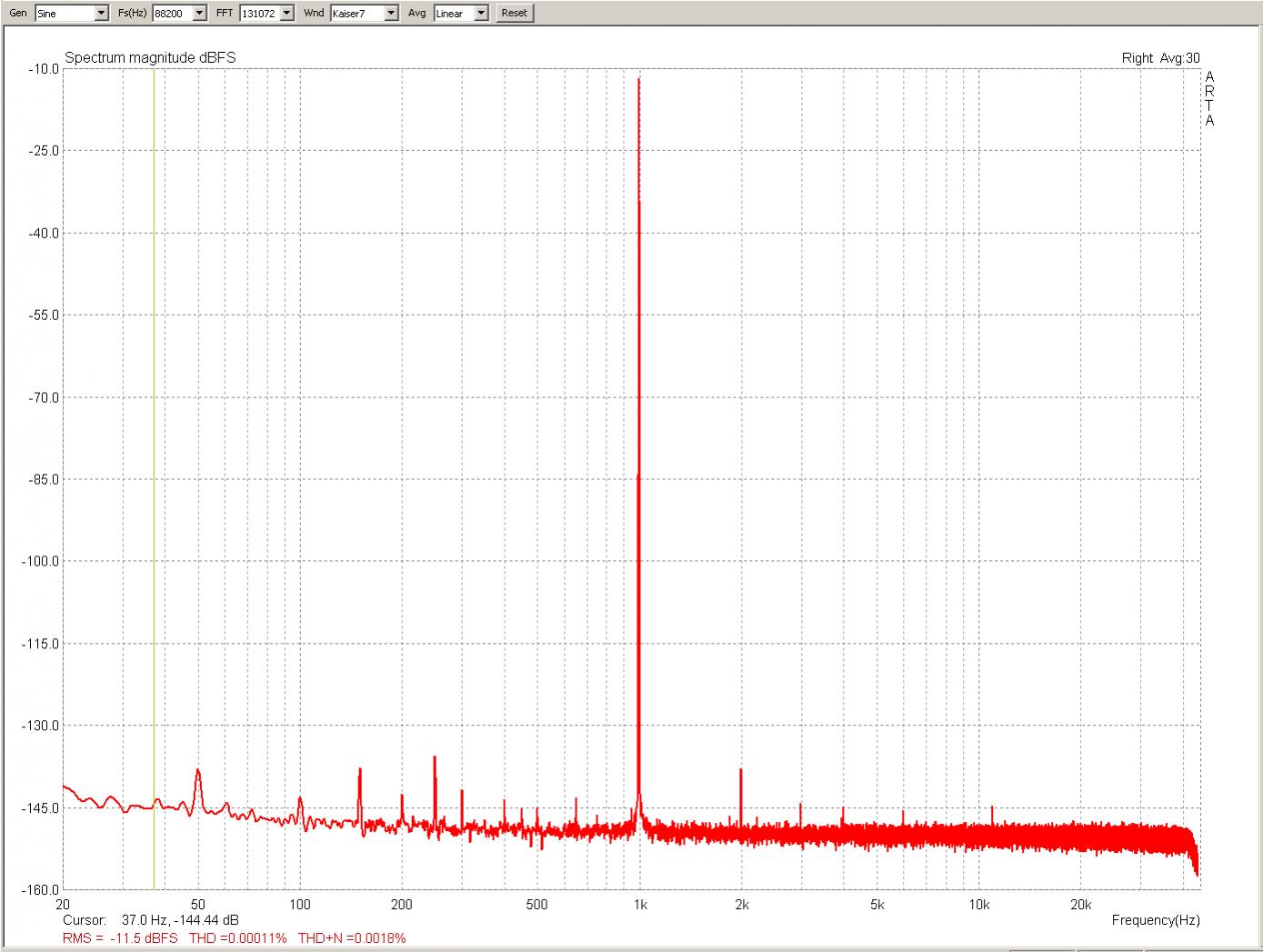
Nevertheless the 0.00011% THD measured by JosephK say it's not that much detrimental, after all
I certainly hope not, but I can't speak for him or account for his thought process.
(..)
To me, that's "work in progress" rather than a release worthy circuit.
Penasa always stated that it was a DIY release, not ready for commercial level.
That doesn't mean that it's not stable or suitable for an high quality DIY amp.
The specs at the end of the document do not make sense.
40 W @ 8 Ω, ±37 V is way low. You should get over 50 W.
56 W @ 4 Ω, ±37 V. Why? At ±28 V, you should get over 65 W, so why are you only getting 56 W at ±37 V?. What's going on there?
It should be the power wasted by the output resistor (remember the 'improved' HCP?).
The circuit Penasa started from is Paravicini's x70 series (P170/270/370, A370) from the eghties, Class A.
Vs the original Class A the My_Ref is still way more efficient.
Damping factor, 8 Ω = >200 (frequency and compensation dependent)??! Okay... So under which conditions were the >200 DF measured? Last I checked, DF = RL/Zout and Zout for a current source should be very high. Is the circuit even a current source then? It's marketed as one...
Not only marketed, from what I understand it's actually so.
The drive capabilities of the My_Ref are one of its strenghts.
S/N (600 Ω): >90 dB (compensation dependent). Again. Under which conditions? The SNR of the MOD86 is 112 dB. That's right at the hairy edge of detection for the APx525.
THD, IMD < 0.05 %. Yeah. Not impressed. I'm getting 0.000067 % THD (1 kHz, 38 W, 8 Ω, ±28 V) and 0.00069 % IMD (SMPTE, 60 Hz + 7 kHz, 38 W, 8 Ω, ±28 V) on the MOD86.
Those measurements were based on the original My_Ref circuit and single sided PCB.
Both the My_Evo and Fremen Edition greatly improved those performances.
The My_Evo parameters are:
Voltage Gain: ~31 dB
Input impedance: 100Kohm 220pFResidual noise (600ohm terminated): <-100dB
Power “base” (measured at pre-tuned clipping): 40Wrms/8ohm or 56Wrms/4ohm
Power “full” (double pump): 50Wrms/8ohm or 80Wrms/4ohm
THD 20hz-20Khz 1-40Wrms/8ohm:Always under -80dB over audio band and all possible power
THD 20hz-20Khz 2-50Wrms/4ohm:Always under -80dB over audio band and all possible power
Dumping factor (8ohm 20hz-20Khz) “base” version: ~180
Dumping factor (8ohm 20hz-20Khz) “full” version: ~350
The My_Evo has an optional second current pump to increase output power.
I'd be interested in seeing the THD+N vs frequency and THD+N vs output power for the circuit as well. The THD+N vs frequency will tell you a lot about the layout, as well as the circuit. I'm curious for the THD+N vs power to see the effects of the clipping circuit you mention.
You can find complete My_Evo JosephK measurements here and Fremen Edition here.
My_Evo:
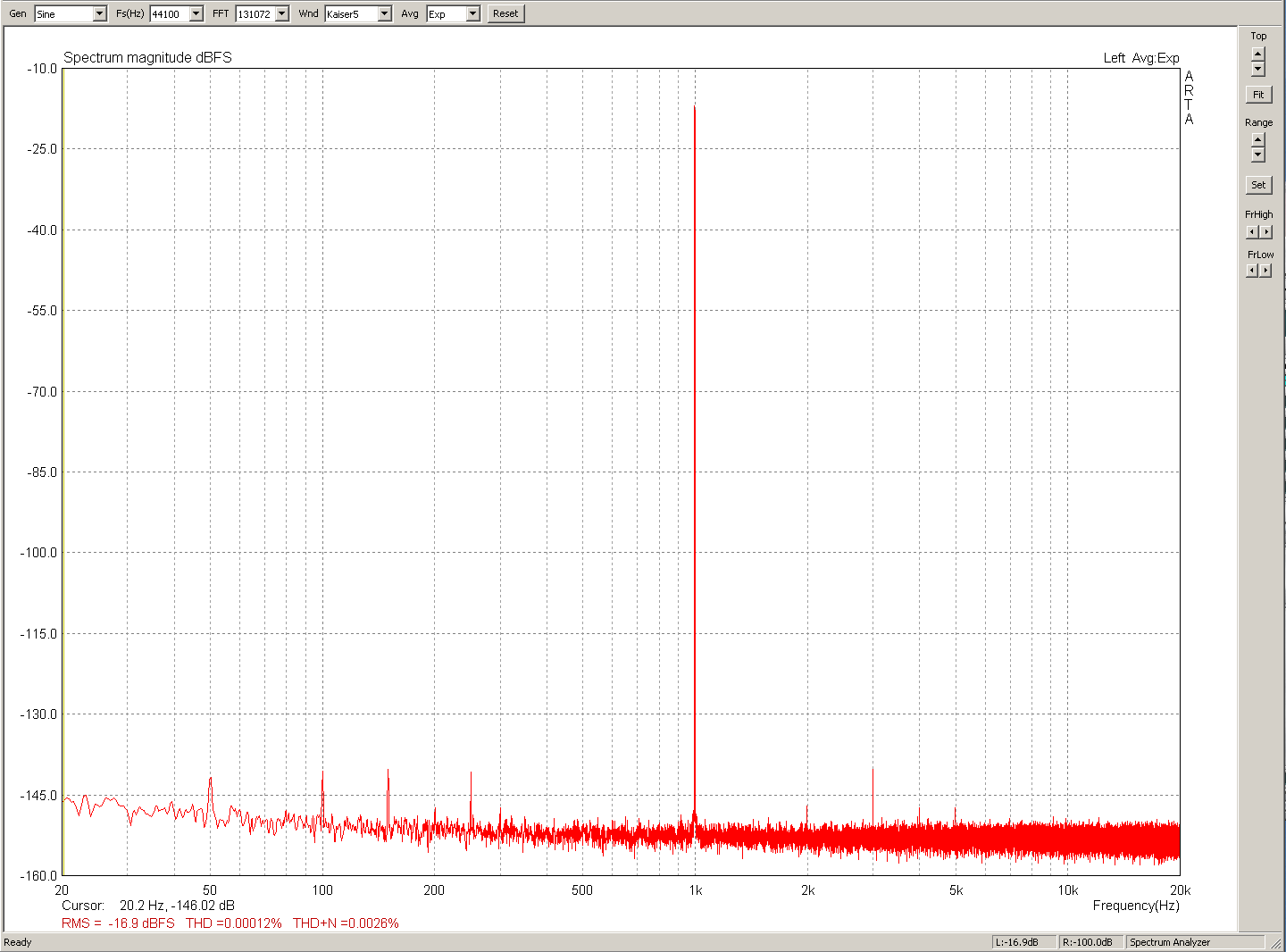
Fremen Edition:
I hope my review of your document was as thorough as you expected.
Really interesting, I appreciate it
Actually I did, way back when Tom first announced his design. If you want the link, I'll post it on here. The funny thing is - he took offense, rather than follow his own advice just given to you
IIRC you also decided to diss THAT and whitlock at the same time. But despite your regulator fetishes the delta in performance from a raw Mod86 sans THAT and the complete chain being a gnat fart.
FWIW I don't think I could blindly tell a difference between the amps being measured. I did buy a Mod86 as I wanted something as a reference that, with sane speakers gave the best performance possible for the money. That may give me an expectation bias ,but as its for me and I'm not going to spout about veils and shimmering string tones on the internet its my issue. It is certainly as neutral as you can get based on current hearing models. And Tom does have the gear to measure properly which helps.
IIRC you also decided to diss THAT and whitlock at the same time.
Dissing doesn't sound at all like me. Perhaps you're just using your normal rhetoric?
But despite your regulator fetishes the delta in performance from a raw Mod86 sans THAT and the complete chain being a gnat fart.
Fetishes? Is that more rhetoric?
There's a customer who's found there's more than a gnat's fart of improvement (subjectively) available to Mod86 when power supply issues are addressed. I'll let you find out who that customer is.
Dissing doesn't sound at all like me. Perhaps you're just using your normal rhetoric?
You said
If you're concerned about subjective SQ (as am I) I'd attack the supplies (meaning lower their impedance) to the THAT chip. It may well be the limiting factor, subjectively as its operating in class B and from the spec sheet there appear to be a number of opamps inside all existing on a rather measly quiescent supply current under 5mA. Hence power supply switching noise looks to be a potential SQ issue.
You pop up everywhere telling people Power supply mods improve things. you clearly have a PSU and regulator fetish. It's fine to admit it, you are amongst friends here.Fetishes? Is that more rhetoric?
There's a customer who's found there's more than a gnat's fart of improvement (subjectively) available to Mod86 when power supply issues are addressed. I'll let you find out who that customer is.
Bovvered? I have seen the measurements and the improvement a fully regulated lab supply makes. Quite literally in the noise and the least of my problems in my system. If someone can hear something 120dB down they are either superman or deluded. Or maybe a bat.
You said
Right - so where is there anything there 'dissing' Bill Whitlock or THAT?
Bovvered? I have seen the measurements and the improvement a fully regulated lab supply makes. Quite literally in the noise and the least of my problems in my system. If someone can hear something 120dB down they are either superman or deluded. Or maybe a bat.
How do you know its under 120dB down when music's a stimulus? All you have are THD+N figures, with sinewave stimulus. Oh and IMD, twin tone.
- Status
- This old topic is closed. If you want to reopen this topic, contact a moderator using the "Report Post" button.
- Home
- Amplifiers
- Chip Amps
- PA03 vs Parallel 86 vs Sympatico vs ??