For a bridged LM4780, e.g. the Sympatico, the datasheet shows 2 Zobels: 2.7 ohm and 0.1uF from + to gnd and - to gnd.
When adding a Thiele network, would the right thing be to put one on each output between amp +/- and +/- speaker terminal?
Datasheet says 0.7 uH and 10 ohm for Thiele. Any reason to change that or Zobel values above?
When adding a Thiele network, would the right thing be to put one on each output between amp +/- and +/- speaker terminal?
Datasheet says 0.7 uH and 10 ohm for Thiele. Any reason to change that or Zobel values above?
The Thiele Network consisting of an Output Zobel located very near the amplifier output devices and the damped inductor located remote from the amplifier are virtually mandatory. The inductor should be OFF BOARD and if possible located away from adjacent metal panels. Midway along the cable from amplifier to output terminal is good.Thanks again. I was thinking that with high impedance, high inductance speaker drivers (many windings on the voice coil) and short cable runs, the Thiele network (L||R) might not be necessary, but perhaps it is. If so, I'd probably place it off the amp board to save on space there.
For a bit of additional RF attenuation I also fit a second Zobel across the speaker terminals. When I use my 8ohms speakers I use a 5r to damp the inductor and then the R+C across the speaker terminals becomes 5r+100nF. That gives a total HF load that is effectively 10r+100nF at the output devices AND 10r+10nF through the inductor, for a final 5r+200nF, when there is no load and no cables.
2Apk into your 16ohms 96dB/W @ 1m speaker gets you to ~111dB @ 1m
That's more than most can get from their speaker. A stereo pair @ 2.4m wll get you to 106dB
And leaves an overhead of 3.5times for transient peak demands to only just hit the guaranteed current output of a single 3886.
2Apk and 16ohms requires a maximum output of 32Vpk and that in turn requires high supply rails. I'd aim for > ±35Vdc, maybe ±38Vdc, if you can ensure you never exceed the absolute max of 84V.
Last edited:
For a bridged LM4780, e.g. the Sympatico, the datasheet shows 2 Zobels: 2.7 ohm and 0.1uF from + to gnd and - to gnd.
When adding a Thiele network, would the right thing be to put one on each output between amp +/- and +/- speaker terminal?
Datasheet says 0.7 uH and 10 ohm for Thiele. Any reason to change that or Zobel values above?
Values in the 1.0 - 2.0 uH range will be good. 0.7 uH probably OK, but I'd need to run a simulation to be sure. 10 Ω is too high and does not sufficiently dampen the resonance formed by the inductor into whatever load cap you have. 1.5 - 3.3 Ω is better. I usually aim for a Q of around 2.0 at 500 kHz.
Each LM3886/LM4780 half should have a Thiele network so in case of the Sympatico, you'll need a Thiele on the + output and one on the - output. I'd try to orient the inductors so they couple as little as possible, i.e. make them perpendicular. And as Andrew said, keep them away from ferromagnetic metals (steel, iron, etc.).
Tom
Andrew T: Good advice, thanks! Of course, your calculations also explain why I'm looking at bridged topologies to get twice the voltage swing of a single channel without worrying too much about the current capacity. I should be able to squeeze through approx 2 A in 16 Ohms with 25 V rails that way, for 64 W into the load. That will be rather loud.
In fact, I designed the speakers with their 16 A midranges with an idea of bridged chipamps in the back of my head. Voltage, not current.
The PHL 1130 goes to 113 dB max SPL, btw. It can take 130 W AES and short term peaks of 90 V, so this is nowhere close to maxing it out.
In fact, I designed the speakers with their 16 A midranges with an idea of bridged chipamps in the back of my head. Voltage, not current.
The PHL 1130 goes to 113 dB max SPL, btw. It can take 130 W AES and short term peaks of 90 V, so this is nowhere close to maxing it out.
Last edited:
The Thiele Network consisting of an Output Zobel located very near the amplifier output devices and the damped inductor located remote from the amplifier are virtually mandatory. The inductor should be OFF BOARD and if possible located away from adjacent metal panels. Midway along the cable from amplifier to output terminal is good.
Any chance we could use this occasion to clear up some terminology. As far as I am aware the Thiele network is just the (series connected) L||R and does not include the Zobel. If you have a reference that says otherwise would love to clear that up as usage is variable.
Asbjbo--acknowledging just how much sensitivity/output you already have speakers-wise, have you done at least a back-of-the-envelope check of how much power you need to achieve the peak loudness you desire? As much as I admire the "too much is just enough" mentality, getting a bridged composite stable might be worth a whole lot less than, say, a working system that still does the job more than satisfactorily. ")
In case you would not wish to redo everything from zero, there had been other people there, doing exactly that: (getting stable a bridged composite lm3886 amp)
http://www.diyaudio.com/forums/chip-amps/255612-bridged-lm3886-lme49720-remote-fb-4.html#post4045037
mzperx project here:
https://docs.google.com/file/d/0BzbIeQI27LjoV21seUw4MG5jQWs/edit
Ciao, George
http://www.diyaudio.com/forums/chip-amps/255612-bridged-lm3886-lme49720-remote-fb-4.html#post4045037
mzperx project here:
https://docs.google.com/file/d/0BzbIeQI27LjoV21seUw4MG5jQWs/edit
Ciao, George
Last edited:
I tried something similar for the Parallel-86. Unless you reduce the DC offset of each LM3886 they will set up a standing current through the ballasting resistors. This lowers the amount of current available for the load and results in rather horrid THD, as in 10x worse than the data sheet performance.
I also found that the two channels of an LM4780 in parallel provided lower THD than two LM3886es in parallel. I suspect this is because of better matching and/or thermal tracking between the Vos of the two channels.
Tom
I like Mod86 much better than Sympatico.
Could you expand? How do they differ?
N.Thiele proposed an Output Network that had both the R+C across the output and the L||R feeding the output.Any chance we could use this occasion to clear up some terminology. As far as I am aware the Thiele network is just the (series connected) L||R and does not include the Zobel. If you have a reference that says otherwise would love to clear that up as usage is variable.
or
The L||R feeding the output and a C across the speaker terminals.
In both cases the C across the the Hot/Flow to Cold/Return is part of his proposal.
Dr E.Cherry did a paper on this and all the infinite versions in between.
I referenced it a few times and posted a spreadsheet to do the Cherry calculations.
The L||R alone is NOT the Thiele Network.
Asbjbo--acknowledging just how much sensitivity/output you already have speakers-wise, have you done at least a back-of-the-envelope check of how much power you need to achieve the peak loudness you desire? As much as I admire the "too much is just enough" mentality, getting a bridged composite stable might be worth a whole lot less than, say, a working system that still does the job more than satisfactorily.
I certainly have, in some detail. 1 W for the tweeters and 3 W for the mids should actually be enough for the levels I'm likely to use. After all, my speakers have very similar drivers to the Pass Rushmore, which were powered by small SuSy Class-A amps as far as I know. But...
Another point is that the basses will be driven by super-clean Hypex NC400's, and the non-existent distortion signature of the Mod-86 seems to be a good match at a slightly lower power level. Still, being an engineer, I tend to speculate about any other ways to solve the problem.
Last edited:
The OPA1611 has lower noise as well. While the OPA1611 is unity-gain stable, it has a really nasty phase wobble around 1 MHz where its internal compensation kicks in. That may disqualify it as a candidate for a composite amp based on the LM3886. Indeed I have gotten some rather interesting behaviour in the MOD86 when I tried the OPA1611. Fun begins when the output voltage approaches clipping and the gain of the LM3886 drops. That seems to slide the crossover frequency down near than phase wobble and suddenly you have a power oscillator.
I'm noticing this pretty clearly in the datasheet (I'm sure it's a little different on your bench). Have you looked at the opa1602, a *little* slower, very similar noise profile, and marginally less beefy output, which is less important in this application anyhow. PSRR and CMRR remain stupidly good. Admittedly, the second channel is lost on you, but good luck buying a single.
Don't mind me: I'm thinking out loud.
And a look at TI suggests that the 49720 remains available in the SOIC package? (Lifetime on the 49740 and 49710, save the to-99). Confusing.
Last edited:
Have you looked at the opa1602, a *little* slower, very similar noise profile, and marginally less beefy output, which is less important in this application anyhow. PSRR and CMRR remain stupidly good. Admittedly, the second channel is lost on you, but good luck buying a single.
The OPA1602 is on par with the LME49720. A hair better voltage noise but a hair worse current noise. Same THD. Lower bandwidth. Meh.
And a look at TI suggests that the 49720 remains available in the SOIC package? (Lifetime on the 49740 and 49710, save the to-99). Confusing.
Confusing indeed. I suspect they have a lifetime supply of the HA's (TO-99) in box stock. No reason to throw them out. Of the LME49710/20/40, only the LME49720MA (SOIC), LME49710HA, and LME49720HA get to survive. The end-of-life notice from TI blamed this on a fab closure, which is bogus. I suspect the bean counters got involved and decided to only keep the big sellers. "Fab closure" sounds better than "we don't feel like making these anymore". My contacts with TI are as confused as I am.
If you look at the other TI audio op-amps, you'll see that they're mostly duals and quads. Not many single op-amps.
Tom
Tom,
I understand You had encountered this problem with your topology, your design.
In the cited project of mzperx he had measured 0.0003% THD at ~1W output, 4ohm, though.
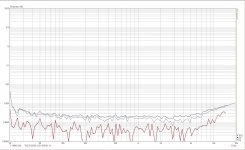
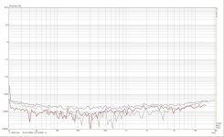
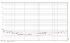
Also, I had been testing a completed, full version of the Mauro Penasa MyEvo amplifier with unselected parallel LM3886 outputs. The parallel version gives better, lower distortion in the high frequecy range than single current pump configuration. Parallel current sources do not fight over dc offsets! I have measured not more than 3mA in the output 'ballast -- no, feedback/control' resistors.
Attached below is the distortion scan at 5W output into 6.8ohm
a) EVO classic, single current pump
b) EVO full, double current pump
C) EVO full at 20W output
Sincerely, George
I understand You had encountered this problem with your topology, your design.
In the cited project of mzperx he had measured 0.0003% THD at ~1W output, 4ohm, though.
Also, I had been testing a completed, full version of the Mauro Penasa MyEvo amplifier with unselected parallel LM3886 outputs. The parallel version gives better, lower distortion in the high frequecy range than single current pump configuration. Parallel current sources do not fight over dc offsets! I have measured not more than 3mA in the output 'ballast -- no, feedback/control' resistors.
Attached below is the distortion scan at 5W output into 6.8ohm
a) EVO classic, single current pump
b) EVO full, double current pump
C) EVO full at 20W output
Sincerely, George
I tried something similar for the Parallel-86. Unless you reduce the DC offset of each LM3886 they will set up a standing current through the ballasting resistors. This lowers the amount of current available for the load and results in rather horrid THD, as in 10x worse than the data sheet performance.
Tom
Attachments
Last edited:
I understand You had encountered this problem with your topology, your design.
The problem of standing current between two LM3886es or the two halves of an LM4780 in parallel are well documented on this forum and are not unique to any particular topology. As I said, the offset voltage of the two amps will differ, hence, a standing current between the two amps results. That is why people use the ballasting resistors. Without the ballasting resistors you'd have a short circuit as one amp half drives the output towards Vos1 * gain and the other towards Vos2 * gain (Vos1 ≠ Vos2). This is a problem with any amplifier that runs multiple channels in parallel.
All I am saying is that the circuit designer needs to deal with this somehow.
You are correct that in a current source amp, you can run multiple channels in parallel without fighting. They'll just add different amounts of current. Instead of having to deal with the DC offsets, you get a stability challenge. This is documented by Bob Pease (see link elsewhere in this thread) and by anyone who has attempted to build a current source amp, including some of the savvy builders on this forum.
All of these problems are solvable. I'm just making the designer(s) out there aware that they exist.
In the cited project of mzperx he had measured 0.0003% THD at ~1W output, 4ohm, though.
That's great. I measure 0.00012 % at 1 W and 0.00020 % at the full output power (55 W into 8 Ω) and 0.00021 % @ 1 W, 0.00033 % at full output power (110 W, 4 Ω) in my Parallel-86. Like I said, the problems or challenges I point out are not insurmountable but they do exist. I think it's reasonable to point them out.
Also, I had been testing a completed, full version of the Mauro Penasa MyEvo amplifier with unselected parallel LM3886 outputs.
You can do that in the BPA200-type circuit as well by adding a DC servo to each LM3886. Wrapping a composite loop around such a circuit can be another challenge, but it's a solvable problem.
The EVO shows good performance, at least on the THD plots. How's the IMD and the transient response with a capacitive load? I'd also be curious for the performance at higher output power than 20 W - how's 100-120 W into 4 Ω looking?
Tom
Last edited:
I think I got it. I simulated an LME49710 as controlling stage in front of an LM3886 as the power stage, added a reasonable mix of compensations around the LME49710, added another LME49710 as unity gain input buffer, and hooked on an RC input filter to make sure that the combo does not try to respond to things that will make the LME49710 panic before the LM3886 responds. And the necessary output RC + L||R filters, of course. Then I wrapped an OPA2277 two op amp DC servo around the composite, duplicated the whole thing and bridged it across the load. The four LME49710s can be implemented as a single quad LME49740, and two LM3886's add up to an LM4780 - exactly what I have in the drawer, a remarkable coincidence.
This is an amazing circuit, both single ended and bridged. Once you find the stable region, it seems quite tolerant for a fairly wide range of gains and compensation capacitor values, also with some allowance for parasitic reactances and reactive loads. 1 kHz square waves are near perfect with just a little bit of leading edge rounding due to the input filter, even with lower gain than a single LM3886 can tolerate. It even seems possible to move some of the gain to the input buffer and run the composite at low gain while respecting the overall gain structure in my replay chain with high efficiency loudspeakers. I still do not quite understand why it works so well, but I also wonder why not all amplifiers are built this way.
I have no idea how the compensation scheme is solved in the Mod-86, but simulation-wise, it seems that both the Sympatico topology (OPA1632 + LM4780) and the one I tried should give near perfect results with no audible degradation. The Sympatico uses a somewhat simpler compensation scheme than what I ended up with, so perhaps it restricts the bandwith a bit more than necessary. My guess would still be that any audible differences are more due to implementation detail than to circuit topology.
Now I only have to buy an Audio Precision test rig and a circuit board fab to test this out in practice and iron out all those implementation details. Perhaps.
Last edited:
- Status
- This old topic is closed. If you want to reopen this topic, contact a moderator using the "Report Post" button.
- Home
- Amplifiers
- Chip Amps
- PA03 vs Parallel 86 vs Sympatico vs ??